In this task you will complete the steps required to duplicate a cavity manually.
In this task, you will:
- Manually create a runner system
- Manually duplicate a cavity
- Check the integrity of the feed system
To build the runner system, you will specify nodes outside the model that the runner system will connect to.
- Open the Modeling Tutorial project.
- Click
 ().
(). - Select the Files of type drop-down list. The list of file types directly supported is shown. Select Study files (*.sdy) .
- Navigate to the tutorial folder, typically C:\Users\Public\Public Documents\Autodesk\Simulation Moldflow Synergy 20xx\tutorial.
- Click the file model_4_material.sdy and click Open.
- Rotate the model to 0 85 90. Enter the values in the Rotation Angle text box
 () and press Enter on your keyboard.
 - In the Layers pane, ensure that the
New Nodes
layer is selected.
You will now create nodes to define the gate and runner system.
- Click
 () to open the Geometry tab.
 - Click
 () and select
  Node by Offset from the Nodes drop-down menu.
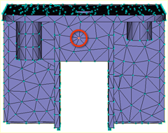
The Node By Offset tool pane appears. You are asked to enter the coordinates of a Reference node in the Base text box. The node you select will become the injection location.
- Select the node indicated below as the Reference node. The coordinates of the selected node appear in the Base text box.
- Click in the Offset text box to activate it. The Measurements dialog appears.
You will not use this dialog as you are going to enter distances directly into the Offset text box in the Tools pane.
- Ensure the cursor is in the Offset text box, enter -10 0 7, close the Measurements dialog, and click Apply. A new node is generated 10 mm in front of the model and 7 mm higher than the Reference node you selected.
- Rotate the model to -90 165 0. Enter the values in the Rotation Angle text box () and press Enter on your keyboard.
- Click
 () to rescale the model and view the new node you created more clearly.
 - Click
 () to change the cursor to the Select cursor.
 - Click in the Base text box in the Tools pane and click the newly created node.
You will now create a second node offset from the first node by 50mm.
- Enter -50 0 0 in the Offset text box and click Apply, then click Close.
- Rotate the model to -65 125 45. Enter the values in the Rotation Angle text box () and press Enter on your keyboard.
- Click () to rescale the model. You should now be able to see both of the new nodes.
- Click
 () and select
  Create Line from the Curves drop-down list.
You will now create a line between the base node you selected on the part and the first node you created.
- Click the node 10 mm from the part.
- Now, click the Reference node you chose to represent the injection location on the part.
Towards the bottom of the Tools pane is the Create as option. It is set by default to Cold sprue . Change this to Cold Gate .
- Click
 next to the Create as box.
The Assign Property dialog appears.
- Click the New button and select
Cold gate
.
The Cold gate dialog appears.
- From the Shape is drop-down list, select
Tapered (by end dimensions)
and then click Edit dimensions...
The Cross-Sectional Dimensions dialog appears.
- Enter 5 in the Start diameter box, and enter 1 in the End diameter box.
- Click OK three times to close the dialog boxes, and then click Apply in the Tools pane.
A line appears in the Model pane. Later in this task, you will mesh the line and the gate characteristics you have selected to be represented graphically.
- To create a curve representing the runner, activate the First Coordinate box and click the node 10 mm from the part.
- The Second Coordinate box is automatically activated; click the node furthest from the part.
- Select the Absolute option in the Coordinates pane.
Note the Second Coordinate values in the Create Curves dialog. They will be used as the reference point coordinates when you duplicate the cavity later in this task.
- Click next to the Create as box.
- Click the New button and select
Cold runner
.
We will accept the default settings of a circular, non-tapered runner, but will edit the runner diameter.
- Click Edit dimensions... and enter a diameter of 6 (mm) in the Cross-Sectional Dimensions dialog.
- Click OK three times, return to the Create Line dialog, and then click Apply.
- Click Close.
The gate and runner system have been modeled for this single part.
- Now you will duplicate the cavity, gate, and runner to create a two-cavity layout. Click
 ().
(). - Click
 () and select
  Reflect from the Move drop-down list.
Note: Using the Reflect tool, you will obtain a mirror image of the part. The Rotate tool will give you a copy of that part.
Reflect from the Move drop-down list.
Note: Using the Reflect tool, you will obtain a mirror image of the part. The Rotate tool will give you a copy of that part. - Select YZ plane from the Mirror drop-down list.
- Activate the Reference point box and then click the node furthest from the part.
The coordinates of the node you created earlier should now appear in the Reference point box.
- Select Copy.
- Select
Attempt connection to existing model
.
When this option is on, automatic adjustments will be made to the model where necessary, for example, merging coincident or very close nodes to ensure that the copied entities are correctly connected to the original entities.
- Click Apply and then Close.
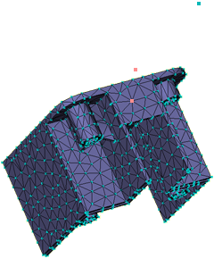
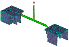
- Rotate the model to -140 140 -35. Enter the values in the Rotation Angle text box () and press Enter on your keyboard
- Click () to rescale the model. There should now be two connected cavities, as shown in the following image:
- Now you will create the sprue. This time we will demonstrate that you can create the required curve directly without first creating nodes. Click
 () and select Create Line from the Curves drop-down list .
 - Activate the First Coordinate box and click the node in the center of the runner.
- In the Second Coordinate area of the dialog, select Relative and enter the coordinates 0 0 50.
- Click next to the Create As text box.
- Click the New button and select Cold sprue .
- From the Shape is drop-down box, select Tapered (by angle) , and click Edit dimensions....
- Enter 6 (mm) in the Start diameter box, and -2 (degrees) in the Tapered angle box.
- Click OK three times to return to the Create Curves dialog and then click Apply.
- Click Close.
- Now that you have created the geometry for the runner system, you must mesh the new curves. Click
 () to open the Mesh tab.
 - Click
 ().
(). - Ensure that
Remesh already meshed parts of the model
is not selected.
It will ensure that only the new curves are meshed.
- Accept the defaults for the other options on the dialog and click Mesh Now.
Note: If the Mesh Generation Tip dialog appears, click Close to continue the meshing operation.
The new curves are meshed and a Mesh Complete message dialog appears. Click OK to close the message dialog.
- The Mesh Log that appears beneath the Model pane provides a record of the mesh generation. Close this pane by deselecting the Logs checkbox.
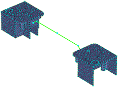
The model should now appear as shown in the following image:
- Now investigate the runner system you have created. Rotate the model to -90 0 0. Enter the values in the Rotation Angle text box () and press Enter on your keyboard. Zoom in on the gate region.
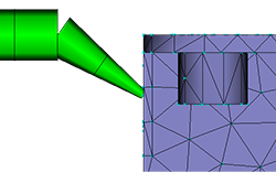
The gate is made up of two beam elements. For accurate modeling, a beam must be made of three or more elements. You must remesh this area to create a more refined mesh. - Click
 ().
(). - Select the beam elements in the gate.
Each of these elements has a unique element number that is displayed in the Entities text box.The Target edge length box shows a current edge length of about 6mm. If this length is reduced, there will be more beam elements in the gate.
- Enter 3 into the Target edge length box and click Apply.
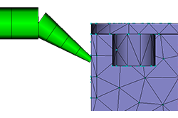
The gate is now made up of four beam elements. - Remesh the gate that connects to the other cavity.
- Now, check mesh connectivity, set the injection node, and analyze. Click
 ().
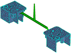
(). - To check the connectivity of the runners with the cavities, click the element at the top of the sprue. Then click Show in the Mesh Connectivity Diagnostic dialog.
- You can see that all the mesh elements are connected.
- Click Close on the Mesh Connectivity Diagnostic dialog in the Study pane.
- Right-click in the Model panel and select
 Mesh Diagnostics to remove the display.
 - Double-click
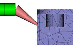
 Set Injection Locations in the Study Tasks pane. When the cursor is moved into the Model panel, it changes shape. This indicates that the injection selection location option is active. Click the top of the sprue.
- Right-click the injection cone and select
Finish Set Injection Locations
. Note that there are
 Check marks beside all the pre-analysis steps and that the
  Start Analysis icon and text is active.
The model is now ready for analysis.
This task has shown you how to create a runner system manually. The runners were created by creating nodes, creating curves connecting those nodes, assigning runner, gate, and sprue properties to the curves, and then meshing the runner system.
Click the Next topic link below to move on to the next task of the tutorial.