To simulate the effect that a load would have on post-molding part stresses, you can set a point load on the model.
Loading conditions are applied in a global coordinate system by default; however, it is often preferable to use a local coordinate system to simplify the load to one direction.
Global Coordinate System
A simple example of a point load acting in a global direction is shown in the following image.
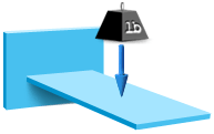
The point is defined by individual nodes. A load of, for example, 0.5 N is applied in the negative Z direction, to the specified node.