Access the venting analysis parameters on the Venting Analysis tab of the solver parameters dialog. The Venting analysis locations grouping option is Off by default. Change the setting to either On (Use vent property ID only) (recommended) or On (Use vent property ID and node connectivity).
If the vent is wide enough so that there are several nodes within the specified vent size, then all nodes within the vent width must be set as venting analysis locations, and these venting analysis locations must be grouped as one vent.
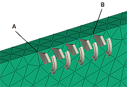
Example: If the vent width is 2 mm, and the distance between nodes A and B is 1.8 mm, then all nodes between A and B, inclusive, must be set as venting analysis locations with the same vent property ID and grouped as one vent.
- Click
 . Cross-hairs appear, allowing you to specify the venting analysis location. The Set Venting analysis location dialog appears, allowing you to select an existing or create a new set of properties (property ID) for the new venting analysis location.
 - Click the cross-hairs on the node where you want to set the venting analysis location and select its property ID.
Repeat this step to set additional venting analysis locations on each node that falls within the specified vent size.Restriction: You must select the same property ID for each venting analysis location in a single group.
- Right-click and select Finish Set Venting Analysis Locations.
- Click
 in the Quick Access toolbar, or click
  then click .