Not all plastic parts have regular cross-sections, that is, are flat on both sides. Analyzing a complex shape such as a grill, requires you to accurately model the exact shape of a part with an extremely fine mesh. This is a time consuming task that requires a high computational overhead.
For Midplane analysis technology, such complex cross-sections can be approximated by representing the area with a thinner, flat cross-section that has an equivalent material volume.
A Midplane mesh does not take into account the edges of the part. A shape factor accounts for the additional surface area in contact with the mold. The shape factor for a surface pattern is defined as the ratio of the actual contact surface to that of the equivalent flat surface.
Supported cross-sectional shapes for triangular elements
Thickness and shape factor are attributes for Midplane triangular elements, similar to diameter and shape factor used for beam elements. When a surface has a regular cross-section, the thickness is specified and the shape factor is equal to 1. However, surface patterns are frequently used in plastic part designs for appearance and functional reasons. There are two ways to model parts with surface patterns: use elements that are smaller than the feature in the surface patterns, or use elements with an equivalent thickness and a shape factor to correct the additional cooling and flow resistance from the surface patterns. The first method could result in a very large number of elements for models with small features in the pattern. The second method is a more efficient way to solve practical problems.
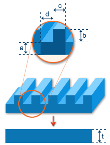
The following diagram shows a slab-like surface. The equivalent thickness and shape factor are calculated from one basic unit of the pattern, which is repeated.
The basic unit of the pattern has a projected area,  ; a contact surface,
  , which includes the top, bottom, and lateral areas; and the volume,
  , between the top and bottom surfaces. For the same equivalent thickness, a larger shape factor means a given volume has more contact surface and has more cooling effects from the wall as well as more flow resistance from the geometric irregularity. The program automatically adjusts these two effects for Midplane elements based on their respective shape factors.
There are two ways to model geometries with grills, depending on the relative dimensions of the grill and the mesh size. If the length of a grill segment is larger than the mesh size, as shown in part (a) of the following diagram, the grills should be modeled by beam elements with the proper equivalent diameter and shape factor. If the grill size is small in relation to the mesh size, the total grid area should be modeled as triangular elements with an equivalent thickness and shape factor, as shown in part (b) of the following diagram.
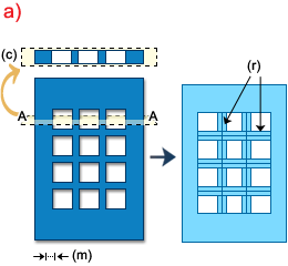
(c) Cross-section A-A, (m) Mesh size, (r) Beam (runner) elements
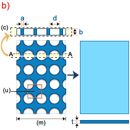
(c) Cross-section A-A, (m) Mesh size, (u) Basic Unit


Worked example
To model a grill with a hole size ( ) of 2 mm and a distance between holes (
 ) of 1.5 mm in a part that is 3 mm thick, first determine an area that is representative of the grill as the basis of the calculations. This is the area
  in the above diagram.
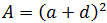
The Projected Area (A) is the area of .
or = 12.25.
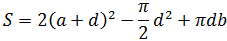
The Contact Surface (S) is [2 x Projected area (top and bottom surfaces)] – [2 x area of the hole] + [Circumference of the hole x hole depth(b)]. This reduces to
. Substituting our values, we get = 37.07.
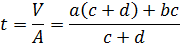
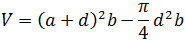
The Volume (V) is [Volume of the Projected area] – [Volume of the hole]. This equals or = 27.33.
The Equivalent Thickness (t) is or 27.33/12.25 = 2.23mm.
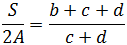
The Shape Factor is [Contact Surface area (S)] / [2 x Projected Area (A)], or 1.51.
Select the grill area on your Midplane meshed model. Right-click and select Properties (alternatively, click  ). In the Cross-section is box, select Other shape. Click Edit dimensions and enter the calculated values for Equivalent thickness (2.23) and Shape factor (1.51) in the Cross-Sectional Dimensions dialog that appears.