A fan gate is a wide edge gate with variable thickness which permits rapid and balanced filling of large parts through a large gate cross-section.
For a Midplane model, a fan gate can be modeled as an extension of the part. First create the outline of the fan gate by adding new nodes, and then create regions within the gate. The regions are assigned different thicknesses so that the gate has variable thicknesses.
- For a Dual Domain mesh, the thickness to width ratio of the cross section is greater than 4:1.
- For a Midplane mesh, the fan gate is modeled with triangular elements and beams.
The following diagram shows a fan gate modeled with triangular elements and beams with thickness variations.
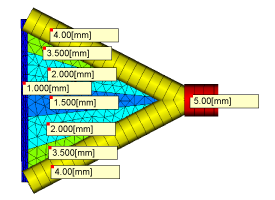
The gate land should be modeled with 3 rows of elements, and the center portion of the gate should be the thinnest section. The thicknesses required depend on the size and shape of the gate, the material being molded, and the injection time. When modeling the gate land, it is critical that all existing nodes of the part be used in the definition of the gate, so the gate and part are attached.
To model a Midplane Fan Gate:
- Use the Nodes tools () to define the shape of the fan gate.
- Click
 ().
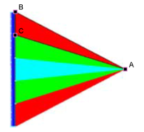
(). - Click on the first node of a region, hold down the control key and select the rest of the nodes forming that region in sequence. In the following diagram, nodes A, B, and C have been selected to form a region.
- Click
 ().
(). - Click New and select Cold gate surface (midplane) from the drop-down list.
- Enter an appropriate thickness for the fan gate region in the Thickness text box.
- Repeat Steps 3-6 for each region in the fan gate, so that the fan gate is thickest at the injection point and thinnest where it joins the part. If additional nodes were created at the gate/part edge, use the stitch tool to connect the gate and the part. Tip: You can create curves on the fan gate sides to emphasize their thickness.
- Click
 () and enter an appropriate mesh density, such that each region in the gate will have at least three rows of triangles.
 - Click
 () and click Mesh Now. The option to remesh already meshed parts of the model should not be used to ensure the new regions have the correct density.