If you have optical birefringence measurements from your own moldings, you may adjust the spectrum correction factor for the specific material you have used in order to obtain more accurate simulation results.
- Select a few typical moldings where the birefringence (retardation or the phase shift) of the moldings has been measured and the processing conditions are known and well defined.
- Measure the birefringence in a few characteristic points on the moldings.
- Run a 3D Warp analysis for the parts using the spectrum correction factor of 1.0.
Note: Select the Birefringence analysis if material data includes optical properties option in the Fill+Pack process settings page when you are setting up the 3D Warp analysis. This ensures that the birefringence results will be generated.
- Compare the simulated birefringence results with your experimental molding results.
- If the simulated birefringence results are over-predicted compared to the experimental results, decrease the spectrum correction factor to values less than 1, for example 0.4 to 0.8.
- If the simulated birefringence results are under-predicted, increase the spectrum correction factor to values greater than 1, for example 1.2 to 1.6.
- If the simulated birefringence results are similar to the experimental birefringence results, use spectrum correction factor values close to 1, for example 0.8, 0.9, 1.1 and 1.2.
- Once you have adjusted the spectrum correction factor value, run the 3D Warp analysis again.
- For each value of the spectrum correction factor calculate the residual mean square error or RMS:
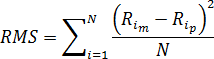
where is the total number of birefringence measurements, and
  and
and  are correspondingly the retardations measured and predicted for the point
  .
. - Plot the graph of RMS versus the spectrum correction factor. The minimum point on the graph corresponds to the optimal spectrum correction factor for the particular material grade.
- Add the material data to your personal database and enter the optimum value of the spectrum correction factor.
- You should use this new material data for future birefringence analyses.