This topic describes how laminae are split across the part thickness and how laminae are used in an analysis.
The Number of laminae across thickness defines the number of layers across the thickness of the part, and can be specified in the Solver advanced options in the Process Settings Wizard. Values that can be specified are 8, 10, 12, 14, 16, 18, and 20.
The following figures show the temperature (X) accross the cavity thickness (Y) at a selected location on the part. The number of results shown on the curve obviously increases with the number of laminae accross thickness.
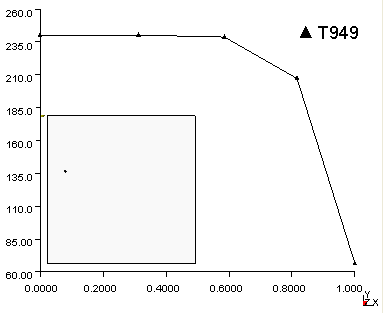
Temperature:XY plot for a part containing 8 laminae accross the thickness of the part.
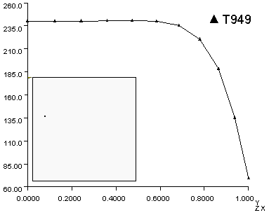
Temperature:XY plot for a part containing 20 laminae accross the thickness of the part.
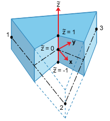
With triangular elements, 0.0 is at the center plane of the thickness, 1.0 is at the positive mold wall, and -1.0 is at the negative mold wall. The positive side is in the positive direction of the normal to the element, defined by the element connectivity and the right-hand rule.
Note that the local x-coordinate is along the direction of node 1 pointing toward node 2. The y-coordinate lies on the plane defined by nodes 1, 2, and 3, and points toward node 3 perpendicular to the x-coordinate. The z-coordinate (or the element normal) is defined by the cross product of the local x- and y-coordinates.
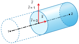
With axisymmetric one-dimensional elements, only half of the specified layers are used in the analysis. In this case, 0.0 is at the center line of the one-dimensional element, and 1.0 is at the mold wall, as shown below. Note that the local x-coordinate of the one-dimensional element lies along the line defined by nodes 1 and 2, and the direction of the x-coordinate is from node 1 toward node 2.
Depending on the thermal boundary condition across the thickness, the actual number of layers used in the analysis is either the specified value or one-half of the specified number of layers across the thickness. Internally defined, non-uniform layer thicknesses are used in the analysis.
Variables such as temperature, velocity, shear rate, and viscosity are stored at the grid point of each layer. As the number of layers used in the analysis increases, a more accurate numerical solution is expected. However, the CPU time required to complete the analysis increases significantly as the number of layers increase. The disk space required to store the results will also increase as the number of layers increase.
The normalized coordinates of grid points are listed in the table below, where zero is at the center line of the thickness and 1 is at the wall.
| 8 | 10 | 12 | 14 | 16 | 18 | 20 |
|---|---|---|---|---|---|---|
| 1.000 | ||||||
| 1.000 | 0.938 | |||||
| 1.000 | 0.926 | 0.864 | ||||
| 1.000 | 0.914 | 0.840 | 0.779 | |||
| 1.000 | 0.900 | 0.816 | 0.743 | 0.685 | ||
| 1.000 | 0.880 | 0.784 | 0.706 | 0.636 | 0.583 | |
| 1.000 | 0.856 | 0.738 | 0.653 | 0.585 | 0.520 | 0.474 |
| 0.816 | 0.681 | 0.577 | 0.508 | 0.453 | 0.397 | 0.360 |
| 0.586 | 0.477 | 0.399 | 0.350 | 0.310 | 0.268 | 0.243 |
| 0.313 | 0.248 | 0.206 | 0.180 | 0.158 | 0.135 | 0.123 |
| 0.000 | 0.000 | 0.000 | 0.000 | 0.000 | 0.000 | 0.000 |
| 0.313 | 0.248 | 0.206 | 0.180 | 0.158 | 0.135 | 0.123 |
| 0.586 | 0.477 | 0.399 | 0.350 | 0.310 | 0.268 | 0.243 |
| 0.816 | 0.681 | 0.577 | 0.508 | 0.453 | 0.397 | 0.360 |
| 1.000 | 0.856 | 0.738 | 0.653 | 0.585 | 0.520 | 0.474 |
| 1.000 | 0.880 | 0.784 | 0.706 | 0.636 | 0.583 | |
| 1.000 | 0.900 | 0.816 | 0.743 | 0.685 | ||
| 1.000 | 0.914 | 0.840 | 0.779 | |||
| 1.000 | 0.926 | 0.864 | ||||
| 1.000 | 0.938 | |||||
| 1.000 |