There are two types of inserts, both of which are modeled similarly.
- Mold inserts are made of metal and are a portion of the mold. They are often used to create a core like feature.
- Part inserts are components that are placed into the mold before the injection phase and ejected with the part. It is assumed there is a new part insert for each shot.
Note: A Midplane mesh can only be used to model simple part insert geometries, such as a brass threaded insert because the thickness of the insert is nearly uniform. For complex geometries, a 3D mesh should be used.
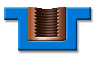
Example of a threaded insert
To create a threaded part insert using a Midplane mesh, apply the following steps.
- Select the elements on the model that touch the insert—typically the side walls of a hollow boss.
- Create a new layer and assign the selected elements to it. This ensures that all the elements are properly selected.
- Click
 ().
(). - Select the elements on the layer that you created in step 2.
- Enter a vector greater than the length of the insert, and remember this vector.
- Click Copy
- Click Apply to copy the selected elements, then click Close
- Select the new elements, then change the property type to Part insert.
- Assign the necessary properties such as material (metal or polymer), interface conductivity and initial temperature if the insert is to be heated.
- Assign the thickness.
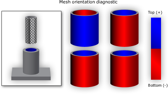
- Ensure the mold insert and the part are correctly oriented by clicking
 (). Note: The orientation of the mesh defines what side of the part the insert is on. If the top side of the insert is touching the top side of the part, the insert is touching the top of the part. If the top side of the insert is touching the bottom side of the elements the insert is on the bottom side of the part elements.