You can run a simulation using part inserts made of materials not found in the Moldflow database, if you enter the material data manually.
This option is available for  3D mesh types only.
To simulate a part insert made of a material that is not in a Moldflow database, you must have the following data about the material available to enter:
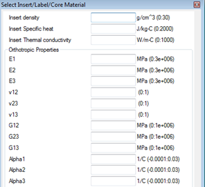
The mechanical properties of the orthotropic material are measured relative to the principal axes. E1 is the Elastic modulus in the 1st principal direction; Alpha1 is the coefficient of thermal expansion (CTE) in the first principal direction.
In addition to the mechanical properties of the material, you are required to enter values into the First Principal axis and Second Principal axis fields at the bottom of the dialog. For every element of the part insert, map the principal axis (used to measure the mechanical properties of the material) to the global coordinate system of the model. If the insert is a flat rectangle, all the elements will have the same values for the first and second principal axes. For part insert elements that are outside of this plane, map their coordinates to the global coordinate system, select all the elements that share the new first and second principal axes and enter the information in the dialog a second time. Repeat the process until all the part insert elements have been mapped.
- Select all the insert elements that share the same first and second principal axes. For a flat, rectangular insert, this would be all of them.
- Right-click and select properties from the drop-down menu.
- Select User-defined orthotropic material from the Material from which this feature is made widget.
- Click Select and enter all the data required by the dialog.
- When all the data for a specific first and second principal axis have been entered, click OK.
- Repeat for every part insert element that has a different first and second principal axis.
- When all the data has been entered, click OK to close the Part insert (3D) dialog.