You need to ensure your model is oriented correctly to correctly calculate clamping effects on the molding process for your part design. The clamp force direction is + Z direction in the coordinate axis. If your model is not oriented so that the clamp force is in the +Z direction, then you need to rotate your model so it is.
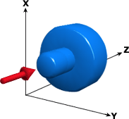
Note: The clamp open direction of your mold must be known so the model can be oriented accordingly in the X, Y, and Z planes.
- In the Layers pane, ensure that nodes are visible.
- Click
 Select and draw a rectangle around the model to select it. Ensure that you have selected the entire model.
 - Click
 ().
(). - Click
 ().
(). - The Select box should contain a long list of node and element numbers, since you have already selected the entire model.
- In the Axis drop-down list, select the axis to rotate the part around.
- Enter the Angle to rotate the part around the selected axis.
- Ensure that Move is selected.
- Click Apply, and then Close.