During Stress or Warp analysis, a load, or force, is applied to the part, and the resulting deflections are measured.
There are several different load types that can be applied, depending on the molding situation you want to simulate.
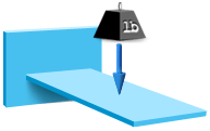
Load Types
The table below lists the types of loads that you can apply to a part. Units for loads must be consistent with the modeling units used.
| Type of Load | Metric | Imperial |
|---|---|---|
| Force (Point) | N | lbf |
| Moment | N.mm | lbf.in |
| Displacement | mm | inch |
| Pressure | MPa | psi |
| Surface | MPa | psi |
| Edge Load | N/mm | lbf/in |
| Thermal Load | °C | °F |
| Volume Load | N/cm3 | inch |
Load incrementation methods
In a large deflection analysis, the total load on the part, whether internal due to the molding process (in the case of a Warp analysis) or externally applied (in the case of a Stress analysis), is applied in a series of steps. This load stepping characteristic of a large deflection analysis allows changes in stiffness of the part as the load increases, that is nonlinear stress-strain behavior, to be predicted and taken into account in determining the deflection of the part under the full load.
There are two ways for this load stepping to occur:
- Loading control
- The load is applied as load factor increments, that is, specified fractions of the total load.
- Displacement control
- The load is specified as displacement increments, that is, specified deflections of a specific node on the part up to the final deflection value at 100% applied load.
The following load incrementation method settings are available:
- Automatic loading control
- Specifies the size of the first load factor increment (the default value is two-tenth of the total load), and then allows the solver to automatically determine the appropriate size for subsequent steps. This is the recommended load incrementation method to use for most cases.
- Manual loading control
- Specifies the first few or all of the load factor increments to be applied to the part.
- Automatic displacement control
- Specifies an initial displacement increment to be applied to a control node automatically selected by the solver, and then allows the solver to automatically determine appropriate displacement increments for subsequent steps.
- Manual displacement control
- Specifies the first few or all of the displacement increments to be applied to the part.
- Arc-length loading control
- In this method, both load and displacement increments are automatically adjusted based on an arc-length constraint within each increment. This method can best follow a complicated post-buckling path.