The following describe the most commonly used part/runner combinations in an injection molding machine.
Direct Injection
This figure represents a simple part-runner system combination, and must be modeled completely unless there are symmetries in the flow path for which occurrence numbers can be specified.
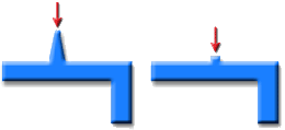
Injection into a multi-gated part

The left half of the picture illustrates a multi-gated cavity which is asymmetrical, thus the whole part and runner system must be modeled. However if the part was symmetrical as in the right hand picture then only one "repeating unit" or flow path of the part need be modeled. Occurrence numbers can be specified to identify how many times the flow paths are repeated.
Injection into a multi-cavity part
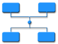
This picture illustrates a multi-cavity layout where, symmetry and occurrence numbers can be used to reduce the amount of modeling work required.