For a Warp analysis, constraints are applied to the model nodes to prevent rigid body motion (global translations and rotations) of the model, in response to the natural warpage of the part.
Automatic vs Manual constraints
By default, and for most cases, automatic constraints can be used to predict the typical deformation of a part.
If no manual constraints were set, then constraints are set automatically, and the deflection of the part is measured using the best-fit technique.
Although an automatic warpage calculation is often sufficient, it can also be useful to set manual constraints on a part in order to predict how it will warp if it is used in particular conditions, or if it is fixed to another object in an assembly for example.
You may want to set non-zero displacement constraints on specific nodes in order to consider assembly-induced deformations and stresses. In order to do this, you need to set rigid body motion constraints on the model first.
Figures 1 and 2 below show how warpage simulations can vary depending on the type of constraints that were set on the part.
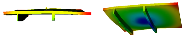
Typical deformation of a part with automatic constraints (scale factor=10.00)
However, setting specific constraints on a part enables early prediction of any unwanted behavior of a part in real conditions of use.
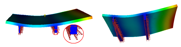
Simulation of the constraints that will be applied on the part when in use, and deflection resulting from these constraints. (scale factor=10.00)