The injection location represents the position where polymer is injected, allowing the software to simulate the flow pattern inside the mold cavity.
This help topic describes some injection location considerations when running a Fill+Pack analysis on a 3D model.
3D Fill+Pack analysis
When you select an injection location on a tetrahedral mesh, the location is associated with a node on the mesh. When a Fill+Pack analysis is performed with no gate modeled, the gate size is automatically assigned based on the part geometry, or in the case of small parts the average facet size of the tetrahedral elements on the surface around the injection location.
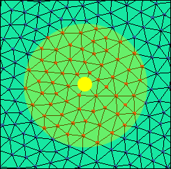
The actual area used for material injection is defined by the number of nodes which fit inside the virtual gate diameter. If a fine mesh is used, the actual injection area will be closer to the virtual gate size than for a coarse mesh. For example, in the first image below the fine mesh size fits well into the virtual gate diameter, but the second image shows that a coarse mesh could produce a smaller than expected gate size.

- If you are using a runner system that is modeled using 1D beam elements, you need to specify only one injection point at the beginning of the sprue or the gate.
- If you are using a runner system that is imported from a CAD model and meshed as tetrahedral elements, you need to specify each of the internal nodes on the polymer entrance face of the sprue (or the gate, if only the gate is modeled). This way, the plastic will be injected through the entire face of the sprue (or gate).
- If the polymer entrance face is far from circular (for example, a long tab), it is best to select a number of injection locations along the centerline of the entrance face and give each of them a sufficient diameter so that collectively they cover approximately the entire area of the entrance face.
- A more accurate representation would be to include more of the feed system in the model geometry, so that the polymer entrance face is circular. If the polymer entrance face is circular, it is best to set the injection location on one node at the center of the entrance face and give it a diameter slightly less than the entrance face diameter. This is to ensure that nodes around the edge of the entrance face are not also set as injection nodes. Note: Do not specify the nodes along the edge of the sprue tip or gate tip, because the elements on the side will also be included in the gate region.
Refer to Setting a gate contact diameter for detailed information about gate contact diameter and how it is used by the solver.
The gate contact diameter affects the rate of cooling during the packing and cooling phases, after the end of fill. Refer to Injection location temperature during packing and cooling for more information.