In this task, you will use various tools to manually repair poor connectivity regions of the study.
Ensure the tutorial_3_task_1 study from the Tutorial 3 project you created in Task 1 is open.
Connectivity Regions: Create Triangles
- Using the ViewCube, select Top View .
- Click
 () to open the Mesh tab.
 - Click
 () to display the mesh Connectivity Diagnostic dialog.
 - Click on any element of the model to serve as the reference element for the connectivity check.
- In the Connectivity Diagnostic pane, select Place results in diagnostics layer.
When the diagnostic is run, this step will ensure that any unconnected elements are placed in their own separate layer. This will help you identify and deal with the problem elements.
- Click Show and then click Close.
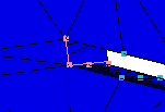
The connectivity plot shows that there is a group of elements in the top left of the model which are disconnected from the rest of the part.
- Click
 () and draw a box around the circular area of disconnected elements.
 - Click
 () and then click in the center of the circle of disconnected elements.
 - Click
 () and examine the connectivity problem.
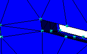
Notice that the disk area is supposed to be connected to the main body of the part at four openings, one of which is shown in Step 16 below. To eliminate the connectivity problem, you need to connect the disk to the main part at these four locations.
- Using the ViewCube, click
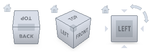 Top View.
 - Rotate the model so that the top hole can be viewed as in the following illustration.
- Click
 () from the Mesh panel drop-down menu.
The Create Triangles dialog appears.
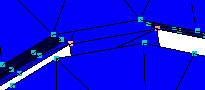
- Select
 (), then with the CTRL button depressed, click on two adjacent nodes on the edge of the disconnected area, and a third node on the main part opposite the first two nodes selected. The selected nodes are shown in pink.
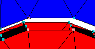
The selected node numbers have been entered in the parameter boxes of the Create Triangles panel.
- Click Apply.
The new triangle is created, and the diagnostic plot is updated.
Because you have bridged the gap between the body of the part and the previously disconnected area, the plot will now show that all elements are connected. Obviously the mesh will need to be built all the way around the four openings before it can be considered fully repaired.
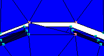
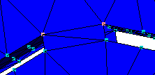
- To continue to fill in the area, use the Create Triangles tool to create another triangle adjacent to the first by selecting the three nodes shown below:
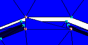
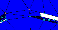
- Rotate the model to display the bottom side of the area you just worked on:
- Repeat steps 16 to 18 to fill in the back side of the mesh:
- Now that you have connected the front and back sides of the open area, you must connect the sides to complete the mesh in this area. You can use the Fill Holes command to perform this task easily.
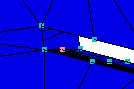
- Rotate the model so that you can see the side areas to be filled in.
- Click
 ().
().
The Fill Hole dialog appears.
- On the model, select the middle node at the bottom of the hole.
- Click the Search button.
Each node on the same edge is highlighted.
- Click Apply and the hole is filled.
- Rotate the model to display the hole on the opposite side, and repeat steps 5 to 7.
- Click Close.
- Click
 ().
(). - Note that there is now only one Connectivity region and that the number of Free edges has been reduced from 54 to 42.
In order to complete the mesh repair, you would repeat both sections of this tutorial on each of the other three open regions of the disk-shaped area.
In the next task, you will learn how to fix high element aspect ratios.
Click the Next topic link below to move on to the next task of the tutorial.