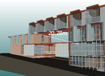
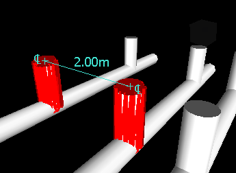
You can use measuring tools to make linear, angular, and area measurements, and to automatically measure the shortest distance between two selected objects.
Endpoints of standard measuring lines are represented as small cross symbols in the Scene View, and all lines being measured by a simple line between registered points.

Endpoints of measuring lines that are snapped to center lines are represented as cross symbols with additional CL markers.

You can change the color and thickness of measuring lines, and toggle the display of dimension label in the Scene View.
Dimension Labels
For distance-based measurements, the dimension label is drawn for each line segment. For accumulative measurements, the dimension label shows the totals, and is drawn for the last line segment. The text is positioned relative to the center point of the line.
For angular measurements, an arc indicator is shown inside the angle, with the centre of the text positioned on the invisible line bisecting the angle. If an angle is too acute, the label is drawn outside the angle. This label is fixed, and does not resize when you zoom in or out, unless the measuring lines become too short on screen to accommodate the arc, in which case it will be adjusted.
The Options Editor enables you to toggle the dimension labels on and off.
For area measurements, the dimension label is positioned at the centre of the area being measured.
Converting Measurements to Redlines
You can convert measurements to redlines. The measurement itself is cleared when it is converted to a redline, and the redline takes the color and line thickness that is currently set for redlining.