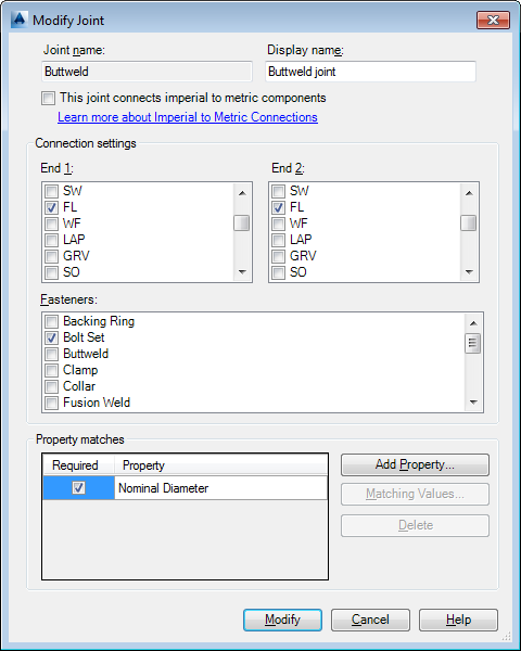
Modifies a joint type.

List of Options
The following options are available in this dialog box.
- Joint name
-
Specifies the new joint name. The name can contain only letters (for example ButtweldReinforcementRing).
- Display Name
-
Can contain spaces and non-letter characters.
- This joint connects imperial to metric components.
-
Selecting a checkbox in this column specifies that the joint connects Imperial (ANSI) and Metric (DIN) components.
If you also want to support connections between same-unit components, use the Add Joint dialog box to add a second joint with similar properties (for example: add MixedButtweld similar to Buttweld).
Joint types that support imperial to metric connections are distinct from same-unit joint types. This allows you to specify matching properties such as 150#, 10PN.
Connection settings
Specifies the end types that the joint connects and the fasteners (if any) that are used.
- End 1
-
Specifies one or more end types (side 1).
- End 2
-
Specifies one or more end types (side 2).
- Fasteners
-
Optional. Specifies the weld type or items that are used to hold the ends together.
Property matches
- Required
-
If selected, the joint cannot be created unless property values match. When clear, the property match is optional. If an optional value does not match, you are asked for permission to connect before the joint is created.
- Add Property
-
Displays the Select Class Property dialog box.
- Matching Values
-
Displays the Set Matching Values dialog box.
- Delete
-
Removes the property.
- Modify
-
Modifies the simple joint type.