Rationalizing a Surface
Dividing a surface
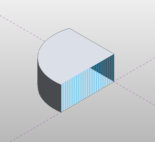
Faces of forms can be divided with UV grids. You can access the data for a divided surface using the DividedSurface.GetReferencesWithDividedSurface() and DividedSurface.GetDividedSurfaceForReference() methods (as is shown in a subsequent example) as well as create new divided surfaces on forms as shown below.
|
Code Region 14-7: Dividing a surface |
public void DivideSurface(Document document, Form form)
{
    Autodesk.Revit.ApplicationServices.Application application = document.Application;
    Options opt = application.Create.NewGeometryOptions();
    opt.ComputeReferences = true;

    Autodesk.Revit.DB.GeometryElement geomElem = form.get_Geometry(opt);
    foreach (GeometryObject geomObj in geomElem)
    {
        Solid solid = geomObj as Solid;
        foreach (Face face in solid.Faces)
        {
            if (face.Reference != null)
            {
                DividedSurface ds = DividedSurface.Create(document,face.Reference);
                // create a divided surface with fixed number of U and V grid lines
                SpacingRule srU = ds.USpacingRule;
                srU.SetLayoutFixedNumber(16, SpacingRuleJustification.Center, 0, 0);

                SpacingRule srV = ds.VSpacingRule;
                srV.SetLayoutFixedNumber(24, SpacingRuleJustification.Center, 0, 0);

                break;  // just divide one face of form
            }
        }
    }
}
|

Figure 60: Face of form divided by UV grids
Accessing the USpacing and VSpacing properties of DividedSurface, you can define the SpacingRule for the U and V gridlines by specifying either a fixed number of grids (as in the example above), a fixed distance between grids, or a minimum or maximum spacing between grids. Additional information is required for each spacing rule, such as justification and grid rotation.
Patterning a surface
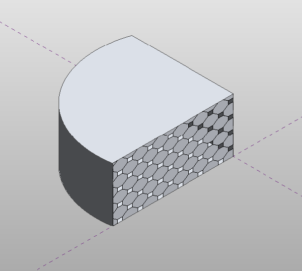
A divided surface can be patterned. Any of the built-in tile patterns can be applied to a divided surface. A tile pattern is an ElementType that is assigned to the DividedSurface. The tile pattern is applied to the surface according to the UV grid layout, so changing the USpacing and VSpacing properties of the DividedSurface will affect how the patterned surface appears.
The following example demonstrates how to cover a divided surface with the OctagonRotate pattern. The corresponding figure shows how this looks when applied to the divided surface in the previous example. Note this example also demonstrates how to get a DividedSurface on a form.
|
Code Region 14-8: Patterning a surface |
public void TileSurface(Document document, Form form)
{
    // cover surface with OctagonRotate tile pattern
    TilePatterns tilePatterns = document.Settings.TilePatterns;
    foreach (Reference r in DividedSurface.GetReferencesWithDividedSurfaces(form))
    {
        DividedSurface ds = DividedSurface.GetDividedSurfaceForReference(document, r);
        ds.ChangeTypeId(tilePatterns.GetTilePattern(TilePatternsBuiltIn.OctagonRotate).Id);
    }
}
|

Figure 61: Tile pattern applied to divided surface
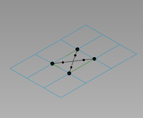
In addition to applying built-in tile patterns to a divided surface, you can create your own massing panel families using the "Curtain Panel Pattern Based.rft" template. These panel families can then be loaded into massing families and applied to divided surfaces using the DividedSurface.ChangeTypeId() method.
The following properties of Family are specific to curtain panel families:
- IsCurtainPanelFamily
- CurtainPanelHorizontalSpacing - horizontal spacing of driving mesh
- CurtainPanelVerticalSpacing - vertical spacing of driving mesh
- CurtainPanelTilePattern - choice of tile pattern
The following example demonstrates how to edit a massing panel family which can then be applied to a form in a conceptual mass document. To run this example, first create a new family document using the "Curtain Panel Pattern Based.rft" template.
|
Code Region 14-9: Editing a curtain panel family |
Family family = document.OwnerFamily;
if (family.IsCurtainPanelFamily == true &&
    family.CurtainPanelTilePattern == TilePatternsBuiltIn.Rectangle)
{
    // first change spacing of grids in family document
    family.CurtainPanelHorizontalSpacing = 20;
    family.CurtainPanelVerticalSpacing = 30;

    // create new points and lines on grid
    Autodesk.Revit.ApplicationServices.Application app = document.Application;
    FilteredElementCollector collector = new FilteredElementCollector(document);
    ICollection<Element> collection = collector.OfClass(typeof(ReferencePoint)).ToElements();
    int ctr = 0;
    ReferencePoint rp0 = null, rp1 = null, rp2 = null, rp3 = null;
    foreach (Autodesk.Revit.DB.Element e in collection)
    {
        ReferencePoint rp = e as ReferencePoint;
        switch (ctr)
        {
            case 0:
                rp0 = rp;
                break;
            case 1:
                rp1 = rp;
                break;
            case 2:
                rp2 = rp;
                break;
            case 3:
                rp3 = rp;
                break;
        }
        ctr++;
    }

    ReferencePointArray rpAr = new ReferencePointArray();
    rpAr.Append(rp0);
    rpAr.Append(rp2);
    CurveByPoints curve1 = document.FamilyCreate.NewCurveByPoints(rpAr);
    PointLocationOnCurve pointLocationOnCurve25 = new PointLocationOnCurve(PointOnCurveMeasurementType.NormalizedCurveParameter, 0.25, PointOnCurveMeasureFrom.Beginning);
    PointOnEdge poeA = app.Create.NewPointOnEdge(curve1.GeometryCurve.Reference, pointLocationOnCurve25);
    ReferencePoint rpA = document.FamilyCreate.NewReferencePoint(poeA);
    PointLocationOnCurve pointLocationOnCurve75 = new PointLocationOnCurve(PointOnCurveMeasurementType.NormalizedCurveParameter, 0.75, PointOnCurveMeasureFrom.Beginning);
    PointOnEdge poeB = app.Create.NewPointOnEdge(curve1.GeometryCurve.Reference, pointLocationOnCurve75);
    ReferencePoint rpB = document.FamilyCreate.NewReferencePoint(poeB);

    rpAr.Clear();
    rpAr.Append(rp1);
    rpAr.Append(rp3);
    CurveByPoints curve2 = document.FamilyCreate.NewCurveByPoints(rpAr);
    PointOnEdge poeC = app.Create.NewPointOnEdge(curve2.GeometryCurve.Reference, pointLocationOnCurve25);
    ReferencePoint rpC = document.FamilyCreate.NewReferencePoint(poeC);
    PointOnEdge poeD = app.Create.NewPointOnEdge(curve2.GeometryCurve.Reference, pointLocationOnCurve75);
    ReferencePoint rpD = document.FamilyCreate.NewReferencePoint(poeD);
}
else
{
    throw new Exception("Please open a curtain family document before calling this command.");
}
|

Figure 62: Curtain panel family

Figure 63: Curtain panel assigned to divided surface