View3D
View3D is a freely-oriented three-dimensional view. There are two kinds of 3D views, perspective and isometric, also referred to as orthographic in the Revit user interface. The difference is based on the projection ray relationship. The View3D.IsPerspective property indicates whether a 3D view is perspective or isometric.
Perspective View
The following picture illustrates how a perspective view is created.
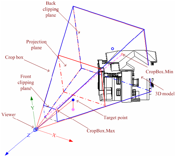
Figure 96: Perspective projection
- The straight projection rays pass through each point in the model and intersect the projection plane to form the projection contents.
- To facilitate the transformation from the world coordinate onto the view plane, the viewing coordinate system is based on the viewer.
- Its origin, represented by the View.Origin property, is the viewer position.
- The viewer's world coordinates are retrieved using the ViewOrientation3D.EyePosition property (retrieved from View3D.GetOrientation()). Therefore, in 3D views, View.Origin is always equal to the corresponding ViewOrientation3D.EyePosition.
- As described in the diagram above, the viewing coordinate system is determined as follows:
- The X-axis is determined by View.RightDirection.
- The Y-axis is determined by View.UpDirection.
- The Z-axis is determined by View.ViewDirection.
- The view direction is from the target point to the viewer in the 3D space, and from the screen to the viewer in the screen space.
The static method View3D.CreatePerspective() method can be used to create new perspective views.
|
Code Region: View3D.CreatePerspective() |
public static View3D View3D.CreatePerspective (Document document, ElementId viewFamilyTypeId; |
The viewFamilyTypeId parameter needs to be a three dimensional ViewType.
The following code sample illustrates how to create a perspective 3D view.
|
Code Region: Creating a Perspective 3D view |
// Find a 3D view type
IEnumerable<ViewFamilyType> viewFamilyTypes = from elem in new FilteredElementCollector(document).OfClass(typeof(ViewFamilyType))
                                                let type = elem as ViewFamilyType
                                                where type.ViewFamily == ViewFamily.ThreeDimensional
                                                select type;
// Create a new Perspective View3D
View3D view3D = View3D.CreatePerspective(document, viewFamilyTypes.First().Id);
if (null != view3D)
{
    // By default, the 3D view uses a default orientation.
    // Change the orientation by creating and setting a ViewOrientation3D
    XYZ eye = new XYZ(0, -100, 10);
    XYZ up = new XYZ(0, 0, 1);
    XYZ forward = new XYZ(0, 1, 0);
    view3D.SetOrientation(new ViewOrientation3D(eye, up, forward));

    // turn off the far clip plane with standard parameter API
    Parameter farClip = view3D.LookupParameter("Far Clip Active");
    farClip.Set(0);
}
|
The perspective view crop box is part of a pyramid with the apex at the viewer position. It is the geometry between the two parallel clip planes. The crop box bounds the portion of the model that is clipped out and projected onto the view plane.
- The crop box is represented by the View.CropBox property, which returns a BoundingBoxXYZ object.
- The CropBox.Min and CropBox.Max points are marked in the previous picture. Note that the CropBox.Min point in a perspective view is generated by projecting the crop box front clip plane onto the back clip plane.
Crop box coordinates are based on the viewing coordinate system. Use Transform.OfPoint() to transform CropBox.Min and CropBox.Max to the world coordinate system. For more detail about Transform, refer to Geometry.Transform in the Geometry section.
The project plane plus the front and back clip plane are all plumb to the view direction. The line between CropBox.Max and CropBox.Min is parallel to the view direction. With these factors, the crop box geometry can be calculated.
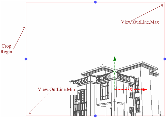
Figure 97: Perspective 3D view
The previous picture shows the projection plane on screen after cropping. The crop region is the rectangle intersection of the projection plane and crop box.
- Geometry information is retrieved using the View.CropRegion property. This property returns a BoundingBoxUV instance.
- The View.OutLine.Max property points to the upper right corner.
- The View.OutLine.Min property points to the lower left corner.
- Like the crop box, the crop region coordinates are based on the viewing coordinate system. The following expressions are equal.
View.CropBox.Max.X(Y) / View.OutLine.Max.X(Y) == View.CropBox.Min.X(Y) / View.OutLine.Min.X(Y)
Since the size of an object's perspective projection varies inversely with the distance from that object to the center of the projection, scale is meaningless for perspective views. The perspective 3D view Scale property always returns zero.
Isometric View
A new isometric view can be created with the static View3D.CreateIsometric() method.
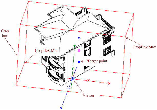
Figure 98: Parallel projection
Isometric views are generated using parallel projection rays by projecting the model onto a plane that is normal to the rays. The viewing coordinate system is similar to the perspective view, but the crop box is a parallelepiped with faces that are parallel or normal to the projection rays. The View.CropBox property points to two diagonal corners whose coordinates are based on the viewing coordinate system.
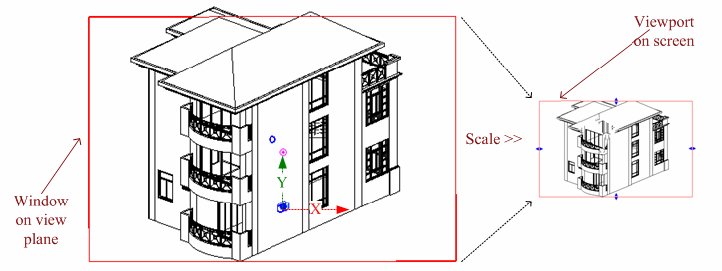
Figure 99: Scale the window on view plane to screen viewport
The model is projected onto a view plane and then scaled onto the screen. The View.Scale property represents the ratio of actual model size to the view size. The related expressions are as follows:
View.CropBox.Max.X(Y) / View.OutLine.Max.X(Y) == View.CropBox.Min.X(Y) / View.OutLine.Min.X(Y) == View.Scale
|
Code Region: View3D.CreateIsometric() |
public static View3D View3D.CreateIsometric (Document document, ElementId viewFamilyTypeId; |
The viewFamilyTypeId parameter needs to be a three dimensional ViewType. Revit determines the following:
- Position of the viewer.
- How to create the viewing coordinate system using the view direction.
- How to create the crop box to crop the model.
Once the view is created, you can resize the crop box to view different portions of the model. You can also change the default orientation. The API does not support modifying the viewing coordinate system.
The following code sample illustrates how to create an isometric 3D view.
|
Code Region: Creating an Isometric 3D view |
// Find a 3D view type

IEnumerable<ViewFamilyType> viewFamilyTypes = from elem in new FilteredElementCollector(document).OfClass(typeof(ViewFamilyType))
                                              let type = elem as ViewFamilyType
                                              where type.ViewFamily == ViewFamily.ThreeDimensional
                                              select type;

// Create a new View3D
View3D view3D = View3D.CreateIsometric(document, viewFamilyTypes.First().Id);
if (null != view3D)
{
    // By default, the 3D view uses a default orientation.
    // Change the orientation by creating and setting a ViewOrientation3D
    XYZ eye = new XYZ(10, 10, 10);
    XYZ up = new XYZ(0, 0, 1);
    XYZ forward = new XYZ(0, 1, 0);

    ViewOrientation3D viewOrientation3D = newViewOrientation3D(eye, up, forward);
    view3D.SetOrientation(viewOrientation3D);
}
|
3D Views SectionBox
Each view has a crop box. The crop box focuses on a portion of the model to project and show in the view. For 3D views, there is another box named section box.
- The section box determines which model portion appears in a 3D view.
- The section box is used to clip the 3D model's visible portion.
- The part outside the box is invisible even if it is in the crop box.
- The section box is different from the crop box in that it can be rotated and moved with the model.
The section box is particularly useful for large models. For example, if you want to render a large building, use a section box. The section box limits the model portion used for calculation. To display the section box, in the 3D view Element Properties dialog box, select Section Box in the Extents section. You can also set it using the IsSectionBoxActive property. In the example below, if the active view is a 3D view, it sets whether the section box is active.
|
Code Region: Showing/Hiding the Section Box |
private void ShowHideSectionBox(UIDocument document, bool active)
{
    if (document.ActiveView is View3D)
    {
        View3D view3d = document.ActiveView as View3D;
        view3d.IsSectionBoxActive = active;
    }
}
|
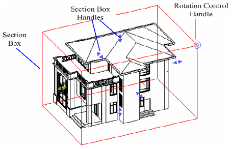
Figure 100: Section box
The View3D.GetSectionBox() and View3D.SetSectionBox() methods are used to get and change the box extents. In some cases, calling View3D.SetSectionBox() can have a side effect. Setting the property to certain values can change the box capacity and display it in the view. To avoid displaying the section box, set the IsSectionBoxActive property to false.
The following code sample illustrates how to change the extents of the section box.
|
Code Region: Changing the extents of the section box |
private void ExpandSectionBox(View3D view)
{
    // The orignial section box
    BoundingBoxXYZ sectionBox = view.GetSectionBox();

    // Expand the section box
    Autodesk.Revit.DB.XYZ deltaXYZ = sectionBox.Max - sectionBox.Min;
    sectionBox.Max += deltaXYZ / 2;
    sectionBox.Min -= deltaXYZ / 2;

    //After reseting the section box, it will be shown in the view.
    //It only works when the Section Box is active
    view.SetSectionBox(sectionBox);
}
|
The coordinates of Max and Min points of BoundingBoxXYZ returned from the GetSectionBox() method are not in global coordinates. To convert the coordinates of Max and Min to global coordinates, you need to convert each point via the transform obtained from BoundingBoxXYZ.Transform property.
|
Code Region: Convert Max and Min to global coordinates |
private void ConvertMaxMinToGlobal(View3D view, out XYZ max, out XYZ min)
{
    BoundingBoxXYZ sectionbox = view.GetSectionBox();
    Transform transform = sectionbox.Transform;
    max = transform.OfPoint(sectionbox.Max);
    min = transform.OfPoint(sectionbox.Min);
}
|
View Locking
The View3D class has methods and properties corresponding to the locking feature available in the Revit user interface.
 The View3D.SaveOrientationAndLock() method will save the orientation and lock the view while View3D.RestoreOrientationAndLock() will restore the view's orientation and lock it. View3D.Unlock() will unlock the view if it is currently locked. The IsLocked property will return whether the 3D view is currently locked.