Use elevation views to look at a project from different locations, either exterior or interior.
- Open a plan view.
- Click View tab
 Create panel
 Elevation drop-down
 (Elevation).
 The cursor appears with the elevation symbol.
- (Optional) In the Type Selector, select a view type from the list, or click Edit Type to modify an existing view type or create a new view type.
- Place the cursor near a wall, and click to place the elevation symbol. Note: As you move the cursor, you can press Tab to change the position of the arrowhead. The arrowhead snaps to perpendicular walls.
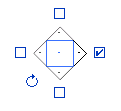
- To set different interior elevation views, highlight the square shape of the elevation symbol, and click.
The elevation symbol displays with check box options for creating views, as the following image shows.
 Tip: The rotation control is useful for aligning to angled elements in the plan.
 - Select the check boxes to indicate where you want to create elevation views.
- Click away from the elevation symbol to hide the check boxes.
- Highlight an arrowhead on the symbol to select it.
- Click the arrowhead once to view the clip plane:

Elevation symbol with clip plane
The end points of clip planes snap and join to walls. You can resize the width of the elevation by dragging the blue controls. If the blue controls do not display in the view, select the clip plane and click Modify Views tab
 Element panel
 Element Properties. In the Instance Properties dialog, select the Crop View parameter, and click OK.
 - In the Project Browser, select the new elevation view.
The elevation view is designated by a letter and number, for example, Elevation: 1 - a.