Creating a mesh of finite elements depends on the selected method of mesh formation and the parameters selected for the method. The following examples demonstrate the principles of mesh creation of planar finite element meshes for both methods:
Coons method
L-Shaped plate and Rectangular plate are two examples of mesh creation using the Delaunay method. The parameters with the greatest influence on mesh creation are displayed in bold face.
EXAMPLE 1
L-shaped plate
FE mesh will be created for an L-shaped plate.
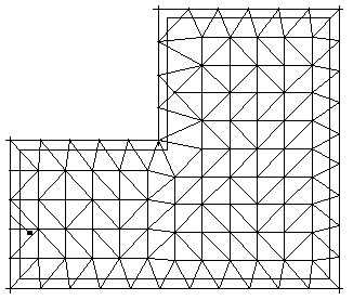
Mesh 1
In the Meshing Options dialog:
- for Available meshing options, select Delaunay
- for Mesh generation, select User, and for Division 1, type 10
- for Delaunay method parameters, select Delaunay
- for Finite elements, select 3-node triangles
- for the remaining parameters, accept the default settings.
The resulting mesh is shown below.
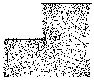
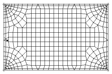
Mesh 2
In the Meshing Options dialog:
- for Available meshing options, select Delaunay
- for Mesh generation, select User, and for Division 1, type 10
- for Delaunay method parameters, select Kang (Hmax=1000, Q=1.2), default emitters checked out (H0=0.3)
- for Finite elements, select 3-node triangles
- for the remaining parameters, accept the default settings.
The resulting mesh is shown below.
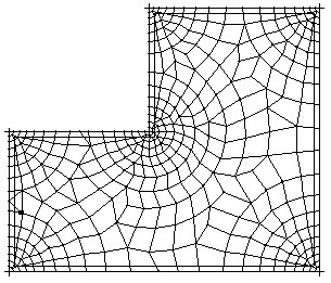
Mesh 3
In the Meshing Options dialog:
- for Available meshing options, select Delaunay
- for Mesh generation, select User, and for Division 1, type 10
- for Delaunay method parameters, select Delaunay+Kang (Hmax=1000, Q=1.2), default emitters checked out (H0=0.3)
- for Finite elements, select 4-node quadrilaterals
- for the remaining parameters, accept the default settings.
The resulting mesh is shown below.
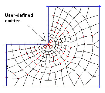
Mesh 4
In the Meshing Options dialog:
- for Available meshing options, select Delaunay
- for Mesh generation, select User, and for Division 1, type 10
- for Delaunay method parameters, select Delaunay+Kang (Hmax=1000, Q=1.2), user's emitters - as shown in the drawing (H0=0.3), default emitters not checked out
- for Finite elements, select 4-node quadrilaterals
- for the remaining parameters, accept the default settings.
The resulting mesh is shown below.
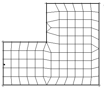
Mesh 5
In the Meshing Options dialog:
- for Available meshing options, select Delaunay
- for Mesh generation, select User, and for Division 1, type 10
- for Delaunay method parameters, select Delaunay (Hmax=1000, Q=1.2), emitters not checked out
- for Finite elements, select 4-node quadrilaterals
- for the remaining parameters, accept the default settings.
The resulting mesh is shown below.
EXAMPLE 2
Rectangular plate
FE mesh will be created for a rectangular plate.
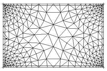
Mesh 6
In the Meshing Options dialog:
- for Available meshing options, select Delaunay
- for Mesh generation, select User, and for Division 1, type 10
- for Delaunay method parameters, select Delaunay+Kang (Hmax=1000, Q=1.2), default emitters checked out (H0=0.3)
- for Finite elements, select 3-node triangles
- for the remaining parameters, accept the default settings.
The resulting mesh is shown below.
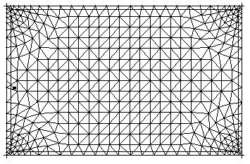
Mesh 7
In the Meshing Options dialog:
- for Available meshing options, select Delaunay
- for Mesh generation, select User, and for Division 1, type 10
- for Delaunay method parameters, select Delaunay+Kang (Hmax=10, Q=1.5), default emitters checked out (H0=0.3)
- for Finite elements, select 3-node triangles
- for the remaining parameters, accept the default settings.
The resulting mesh is shown below.

Mesh 8
In the Meshing Options dialog:
- for Available meshing options, select Delaunay
- for Mesh generation, select User, and for Division 1, type 10
- for Delaunay method parameters, select Delaunay+Kang (Hmax=1.0, Q=1.2), default emitters checked out (H0=0.3)
- for Finite elements, select 3-node triangles
- for the remaining parameters, accept the default settings.
The resulting mesh is shown below.
Mesh 9
To consolidate an FE mesh (mesh 8): In the Mesh consolidation dialog, for
Conversion coefficient, type 0.3, which is the consolidation operation for all elements.
The resulting mesh is shown below.
Delaunay method
Quadrilateral plate and triangular plate are two examples of mesh creation using the Coons method. The parameters with the greatest influence on mesh creation are displayed in bold face.
EXAMPLE 1
Quadrilateral plate
FE Mesh will be created for a quadrilateral plate.
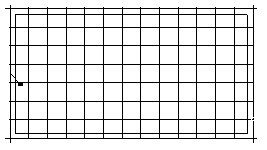
Mesh 1
In the Meshing Options dialog:
- for Available meshing options, select Coons
- for Mesh generation, select User, and for Division 1, type 10
- for Coons method parameters, select squares in rectangular contour
- for Finite elements, select 4-node quadrilaterals
- for the remaining parameters, accept the default settings.
The resulting mesh is shown.
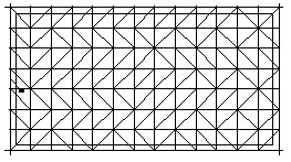
Mesh 2
In the Meshing Options dialog:
- for Available meshing options, select Coons
- for Mesh generation, select User, and for Division 1, type 10
- for Coons method parameters, select triangles in rectangular contour
- for Finite elements, select 3-node triangles
- for the remaining parameters, accept the default settings.
The resulting mesh is shown below.
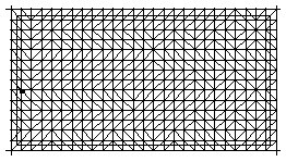
Mesh 3
To refine an FE mesh (mesh 2): In the Mesh refinement dialog, for Mesh refinement type, select double, which is the refinement operation for all elements. The resulting mesh is shown below.
EXAMPLE 2
Triangular plate
FE mesh will be created for a triangular plate.
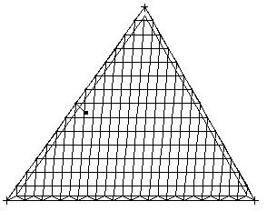
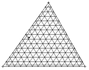
Mesh 4
In the Meshing Options dialog:
- for Available meshing options, select Coons
- for Mesh generation, select User, and for Division 1, type 10
- for Coons method parameters, select triangles and squares in triangular contour
- for Finite elements, select 3-node triangles
- for the remaining parameters, accept the default settings.
The resulting mesh is shown below.
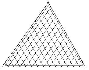
Mesh 5
In the Meshing Options dialog:
- for Available meshing options, select Coons
- for Mesh generation, select User, and for Division 1, type 10
- for Coons method parameters, select triangles and squares in triangular contour
- for Finite elements, select 4-node quadrilaterals
- for the remaining parameters, accept the default settings.
The resulting mesh is shown below.
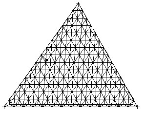
Mesh 6
To refine an FE mesh (mesh 5): In the Mesh refinement dialog, for Mesh refinement type, select simple, refinement operation for all elements.
The resulting mesh is shown below.
Mesh 7
To consolidate an FE mesh (mesh 6): In the Mesh consolidation dialog, for
Conversion coefficient, select 0.3, consolidation operation for all elements.
The resulting mesh is shown below.