3D Spring Support Dialog Box
The word Fixed in the 3D Spring Support dialog box for earlier versions of the software has been changed to Constrained for the 2015 Product Enhancements release. This term more accurately reflects the fact that the X, Y, and/or Z translations or rotations are not rigidly held (fixed). Rather, they are constrained using springs of the specified stiffness. Small displacements or rotations of the constrained vertices, surfaces, or edges are possible.
Apply Mesh Refinement to Construction Vertices
You can now select one or more Construction Vertices and apply mesh refinement using the Mesh Refinement Add to Selection command. You can also use the Add Refinement Point command in the context menu that appears when you right-click with one or more construction vertices selected. Prior to the 2015 Product Enhancements release, refinement could only be applied to surfaces, edges, or regular vertices.
Collapse Part Details
A new command, Collapse Part Details, has been added to the context menu that appears when you right-click the Parts heading in the browser. This command collapses the individual part branch so that only the part number and name remain visible. Previously, this action could only be performed using the keyboard shortcut Ctrl-Shift-M. When simultaneously defining the element type, element definition, or material for multiple parts, collapsing the part details makes selection of a range of parts easier.
Color Options for Imported CAD Models
In prior versions of Simulation Mechanical, CAD models that include supported part color information dictated the color of parts within Simulation Mechanical. In the absence of supported CAD part color data, the legacy Simulation Mechanical colors would be assigned. With the 2015 Product Enhancements release, you now have a choice. You can choose to override CAD-based colors with Simulation Mechanical colors.
For example, suppose your CAD package assigns colors by material and that you have a large, multi-part assembly where all parts are steel. Such models appear as all gray, which makes distinguishing the various parts more difficult. The Simulation Mechanical color scheme assigns a unique color to each part.
Location of the color options:
Click Tools Options Application Options and go to the CAD Import tab.
The following two color options appear as radio buttons in the Initial CAD rendering options section of the dialog box:
- Use CAD color: Select this option to render the model within Simulation Mechanical using the colors defined in the CAD model. This option is ignored if the model does not contain supported part color data.
- Use simulation color: Select this option to override the CAD colors and apply the legacy Simulation Mechanical color scheme to all parts. This color scheme assigns green for Part 1, red for Part 2, then yellow, cyan, brown, and so on.
Contact Context Menu (Linear Static Stress)
The contents of this context menu have been rearranged for better clarity. Contact types are now organized into three groups, as follows:
- Bonded, Welded, and Free/No Contact
- Surface Contact, Sliding/No Separation, Separation/No Sliding, Shrink Fit/Sliding, and Shrink Fit/No Sliding
- Edge Contact
Create Solid Mesh Command
The Create Solid Mesh command is available from the ribbon (Mesh Mesh Create Solid Mesh) and from a context menu. The ribbon command has not been changed. However, the associated context menu command has been relocated for the 2015 Product Enhancements release.
Previously, the Create Solid Mesh command was located in the top-level of the Part context menu (accessed by right-clicking the Part headings). It is now located in the CAD Mesh Options pull-out menu within the Part context menu. In addition, you can directly access the Create Solid Mesh command by right-clicking the CAD Mesh Options headings in the browser. This new command location is consistent with the 2015 and earlier online Help.
Delete CAD Mesh Command
The Delete CAD Mesh command was previously only available from the Mesh tab of the ribbon. In the 2015 Product Enhancements release, this command is now available from the context menu that appears when you right-click on one or more selected Part headings. Specifically, this command now appears within the CAD Mesh Options pull-out menu of the Part context menu.
Delete Selection Groups using the Keyboard
You can now delete one or more selection groups by selecting them in the browser and pressing the <Delete> key on the keyboard. Prior to the 2015 Product Enhancements release, you had to delete selection groups using the Delete command on the ribbon or in the context menu that appears when right-clicking a selection group heading.
Element Type Context Menu in Browser (All Analysis Types)
The contents of this context menu have been rearranged into a clearer, more structured order. Element types are now organized into three groups, as follows:
- 3D geometry (solid elements, brick and tetrahedron)
- 2D geometry (2D and planar elements, such as plate and shell)
- 1D (line elements, such as beams, thermal rods, and actuators)
Hydrostatic Pressure Dialog Box
The letter used to represent a point on the fluid surface has been changed from P to S. This change makes the Hydrostatic Pressure dialog boxes for both linear and nonlinear analyses consistent with the Help documentation.
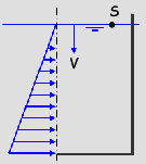
Point on Fluid Surface (S)
Lines in Sketches – Reworded Option
When adding lines to sketches, a default type can be defined within the application options. New sketch lines can default to construction lines or regular lines. Construction lines are suitable for 2D mesh outlines or for use with structured meshing tools. Regular lines are suitable for 1D elements (such as trusses, beams, thermal rods, springs, gap elements, and actuators).
The previous label for the line type option has been reworded. The new option is Use construction lines by default when drawing lines. To find this option, click Tools Options Application Options Sketching. The option checkbox is enabled by default, producing construction lines. Disable this option if you more frequently draw actual line elements on sketch planes.
Number of threads/cores for solid meshing Revised Option Name
The legacy All option has been renamed Automatic/All. To reach this option, click Mesh Mesh 3D Mesh Settings Options Model Number of threads/cores for solid meshing.
The option name was changed to Automatic/All to more accurately reflect the program behavior. The solid meshing process uses a single core to mesh a part but can mesh multiple parts in parallel, providing the needed processor cores are available. If the number of cores exceeds the number of parts, not all of the cores are used. For example, if your computer has eight cores and your model has five parts, the solid meshing process uses five cores (not all eight). Conversely, if the number of parts exceeds the number of cores, all cores are used, but all parts cannot be solid meshed concurrently.
Out-of-Date Results – Simplified Warning Message
After having run a simulation, if you change the mesh, geometry, parameters, or setup (loads, constraints, and so on), the stored results are no longer consistent with the current model in the FEA Editor. A warning appears if you try to enter the Results environment. That message has been simplified for the 2015 Product Enhancements release. The new message is as follows:
The results are out-of-date as the model has changed.
Do you wish to see the old results anyway?
Click Yes to proceed to the Results environment with the old results displayed. Otherwise, click No.
Torque Coefficient (K) for Bolts
When you create a bolt using the command Mesh CAD Additions Bolt command, you have the option to specify a Preload magnitude. You can specify an axial force or a torque. For the latter case, you must specify a Torque coefficient (K) in addition to the torque magnitude.
Previously, this data field was labeled Friction factor (K). The input has been renamed to avoid confusion with the friction coefficient used for different situations. The relationship between the axial force (Fi), the tightening torque (T), the torque coefficient (K), and the bolt diameter (d) is defined by the following equations:
With a nut:
- Fi = T / (K*d)
Without a nut:
- Fi = T / (1.2*K*d)
Rename Multiple Parts in One Operation
With the 2015 Product Enhancements release, you can now select multiple parts and Rename all of them in one operation. This is convenient when the same name is appropriate for a set of bolts, joints, gussets, or similar components. Select two or more parts in the FEA Editor environment (within the browser or display area) and right-click. The Rename command is now available within the context menu that appears. For prior software versions, when multiple parts were selected, the Rename command was not available.
Renamed Nonlinear Material Models
To avoid potential confusion with similar material names, the following nonlinear material models have been renamed:
| Legacy Name | New Name |
|---|---|
| Thermoelastic: | Temperature Dependent Isotropic |
| Thermoplastic: | Temperature Dependent Plasticity |