A frequent application for Mechanical Event Simulation (MES) is to determine how well a product will survive a fall onto a hard surface. MES allows you to estimate such events without having to make prototypes and perform actual drop tests in a lab. The Drop Test Wizard automates the process of setting up a drop test simulation.
To start the Drop Test Wizard, click the Setup  Model Setup Drop Test (
 ) command. The procedure for completing the wizard in outlined below.
Step 1: Which Parts to Include
Choose which parts of your model to include in the drop test simulation. The choices are...
- All
- Let me choose...
If you click the Let me choose... radio button, a list box appears, along with an Add and a Remove button. Select the desired parts, either within the display area or using the browser (tree view), and click the Add button. If you wish to remove any item, select the part or parts within the list in the Drop Test Wizard dialog box and click the Remove button.
When you click the Next button, any part not included in the drop test will be deactivated and the wizard will advance to the second step.
Step 2: Drop Height, Gravity, and Impact Plane Options
On the second dialog box of the wizard, you specify the following items:
- Height form which your model will be dropped. There are two options...
- Drop Height H measured from lowest point. For this option, an impact plane will be created at the specified distance below the lowest point on the model (with the direction consistent with the gravity direction).
- Drop Height H measured from selected point. For this option, you can either enter the X, Y, and Z coordinates in the provided input fields, or select a vertex on the model and click the Select button.
- Gravity (g). The standard gravitational acceleration constant will be pre-defined in the current display units. You can also change the value to simulate higher or lower acceleration rates.
- Set direction of gravity. Use this drop-down list to choose any of the six global directions: +/-X, +/-Y, or +/-Z.
- Create Impact Plane. If an impact plane has been created previously by the Drop Test Wizard, this button will instead be labeled Modify Impact Plane. Click this button to either create the impact plane or to update the definition of a previously created impact plane.
- Fully general. This is the default type of impact plane for a drop test. The model can bounce off of the plane after impact or slide along it. If you wish to prevent bouncing and allow only sliding contact, click this button and choose the alternative Slide / no bounce option from the drop-down list. Once a point or surface of the model contacts the impact plane, it will not separate from it when the Slide / no bounce option is specified.
- Create/modify impact plane when Next button is clicked. When this checkbox is activated, you do not have to separately click the Create Impact Plane or Modify Impact Plane button. The action will occur automatically when you click the Next button to advance to step 3. This option is activated by default.
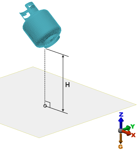
Figure 1: Drop Test Example (Gravity in -Z Direction, H Based on Lowest Point on Model)
Step 3: Initial Velocity
In this step, you specify what the velocity of the model is at the beginning of the simulation event. The following options are available...
- Stationary. The initial velocity is zero.
- Moving. When this option is selected, you specify the components of the Initial velocity (V0) in the X, Y, and Z input fields. The assumed initial velocity can be in any desired resultant direction.
- Apply Load. Click this button to apply the initial velocity to all active parts of the model. This button will only appear if the Moving radio button is selected.
- Apply/modify velocity load when Next button is clicked. This option will only appear if the Moving radio button is selected. When this checkbox is activated, you do not have to separately click the Apply Load button. The velocity will be applied when you click the Next button to advance to step 4. This option is activated by default.
Step 4: Event Intervals, Durations, and Capture Rates
The Estimated time until impact and the Estimated velocity at impact are calculated automatically and displayed in the fourth dialog box of the Drop Test Wizard.
The event is automatically divided into three analysis intervals, as follows:
- Event 1 – Drop: The time preceding the impact. A small capture rate (large time step size) is used for this interval since there is no significant stress or deformation in the model during free fall.
- Event 2 – Impact: A short time period in which the impact occurs. A large capture rate (small time step size) is used in this interval to accurately capture the rapidly occurring stress and deformation during the impact event.
- Event 3 – Rebound: A period of bouncing or sliding after the impact has occurred. The duration of this interval is equal to the sum of the Drop and Impact interval times, by default. A course time step is calculated for this interval, though it is typically finer than that of the Drop interval.
The Automaticoption is selected by default. If you wish to modify the event durations or numbers of steps, deactivate this option. You cannot directly change the Capture Rate. The numbers in this column are calculated from the specified Duration and number of Steps. Likewise, the numbers in the Total Timecolumn cannot be altered directly. These numbers are the cumulative sum of the individual interval durations and are calculated automatically.
Click the Next button to proceed to Step 5.
Step 5 – Run the Simulation Now?
On this final dialog box, you will be asked whether or not you are ready to run the simulation. The choices are:
- Yes. When this option is selected, the wizard will be closed and the analysis will be started as soon as you click the Finish button.
- No, I need to do additional setup. When this option is selected, clicking the Finish button will exit the Drop Test Wizard, but not initiate the simulation. Use this option if you want to make any other adjustments to the model setup before running the simulation or if you simply want to postpone the simulation.
Notes:
- For the second and subsequent steps, click the Backbutton to return to the previous setup step.
- Click the Cancel button at any step to exit the wizard. However, any parameters that you have defined and any impact plane you have created will remain. If you later click the Drop Test command again, it will resume from where you last left off.
- If you wish to remove an impact plane created by the Drop Test Wizard, you will have to delete it manually. The plane will be listed under the Impact Planes branch in the browser.
- If you wish to change the elevation of the impact plane, do so using the Drop Test Wizard so that the drop interval duration is automatically updated. Do not edit the impact plane directly, because the event duration will not be updated as needed.
- When the Drop Test Wizard is used, a parameter within the Integration tab of the advanced analysis parameters is altered. Specifically, the Parameter for (MES) integration method will be changed to zero (the default value is 1). A parameter of zero prevents high-frequency effects from being filtered out during the solution and also maintains a greater accuracy of the impact time and impact velocity results. For more information, refer to the General MES, NLS Integration Method section of the Integration Methods page.
Drop Test Wizard Limitation (Model Rotation)
The Drop Test Wizard does not take rotation of the model into account when estimating the impact time. Only vertical and horizontal initial velocities and gravitational acceleration are considered. If an initial rotational velocity, or a force, pressure, or moment load is applied to the object such that the tilt of the model relative to the floor is altered during the drop interval, the impact time will be affected. To properly capture the impact event, you will have to manually adjust the duration of the drop interval in these cases.