A pulley element can be added to any MES model. This element consists of three nodes: driver, pivot and slack. The pivot node is located at the center of the pulley. The driver node is the node on the cable whose displacement controls the displacement of the slack node. When the driver node moves a certain distance, the slack node will move some factor of that distance. The cables in the pulley element are assumed to be perfectly rigid.
How to Add Pulley Elements to Models
Unlike other elements, the pulley element must be added in the FEA Editor environment by selecting Draw Design Pulley Element (or by right-clicking in the display area with nothing selected and selecting Add Pulley). The Pulley Element Definition dialog will appear.
Since each pulley must be in its own part, the Target Part field is disabled but shows which part number the added pulley will be assigned.
Next, you must specify the three nodes: the center of the pulley (the Pivot), and the two ends of the cable passing over the pulley (the Driver and Slack nodes). You can either enter the absolute coordinates in the appropriate fields or you can press the Select button. This button will take you back to the display area. You can click an existing node in the model and the coordinates of that node will be entered in the fields. For example, if you are going to connect the pulley to a node on a brick element part, you can press the Select button in the Pivot row and click the node on the brick element part.
When you have defined all three nodes, press the OK button. A new part heading will be added to the tree view assigned as pulley elements. Also two connected line segments will appear in the display area.
- Neither node should come into contact with the pulley during the analysis; otherwise, the physics of the pulley become violated. Place the Driver or Slack node far enough from the pulley so that the motion does not move the node into the pulley. (If the motion is in one direction, the node that moves away from the pulley can be relatively close to the tangent point. If the motion is back and forth, both nodes must have enough distance from the pulley to allow free motion.)
- The direction of wrap around the pulley is determined by the three points specified. Some arrangements produce an ambiguous wrap direction. Placing the nodes so that they remain far from the pulley throughout the analysis will remove the ambiguity.
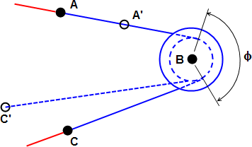
The pulley (shown in blue) is defined by the Driver (point A), Pivot (point B), Slack (point C), and the Pulley Radius (see below). The other elements connected to the pulley – such as truss elements – are shown in red. As point A moves to A', point C moves a corresponding distance to point C'. The wrap angle (φ, as shown in the figure) is determined by the software and may change during the analysis.
Pulley Element Parameters
You can complete the definition of the pulley element by right-clicking on the Element Definition heading for that part in the browser (tree view) and selecting the Edit Element Definition command.
There are three parameters that are used to define the geometry and behavior of the pulley element.
- Pulley Radius: In this field, specify the radius of the pulley, measured from the pivot node to the point on the pulley that contacts the surface of the cable. This pulley radius will be added to half of the cable thickness to calculate the effective radius (that is, the pitch radius) through which the cable will travel. When either the driver or slack node is within this radius of the pivot node, the pulley will become locked.
- Cable Diameter: Specify the diameter of the cable in this field. Half of the cable diameter will be added to the inner radius of the pulley to calculate the effective radius (or pitch radius) through which the cable will travel.
- Amplification Factor: Specify the amplification factor of the pulley in this field. The amplification factor will be used to determine the displacement of the slack node when the driver node moves. If the amplification factor is 2, the slack node will travel half the distance of the driver node. A simple pulley has an amplification factor of 1. Use values greater than 1 to represent block and tackle or geared pulley arrangements, where the cable tension is amplified but the load moves a lesser distance. Values less than 1 can also be specified, in which case the slack node moves further than the driver node but with reduced cable tension (or load) relative to the tension at the driver node.
There are two additional parameters that are used solely for visualization of the pulley in the Results environment. These parameters have no effect on the behavior of the pulley:
- Pulley Outer Radius: Specify the outer radius of the pulley in this field.
- Pulley Width: Specify the width (or thickness) of the pulley in this field. The width is perpendicular to the plane defined by the three nodes.