An actuator element is a single line that can be in an arbitrary direction. One node of the actuator element is considered the master, and the opposite node is the slave. During the analysis, the slave node will be able to translate or rotate relative to the master node following a load curve, simulating a hydraulic cylinder or motor. The master node must be constrained or attached to the structure, and the slave node must be attached to the structure.
There are three types of actuator elements that can be used in an analysis. The type of actuator element can be selected in the Type of actuation drop-down box in the Element Definition dialog box.
- If only the distance between the two nodes will be prescribed, select the Distance (displacement) option. The rotation of the structure applied to the actuator elements can be free or forced to be equal depending on the options selected (see Actuator Element Constraints below).
- If the distance between the nodes will not be controlled, but the slave node will undergo a prescribed axial rotation relative to the master node, select the Relative axial rotation option. An axial rotation is defined as a rotation about the line between the two nodes of the actuator element. Note that the slave node will be free to translate relative to the master node as a reaction to the applied loads. The actuator can get longer or shorter.
- If the distance between the two nodes will be prescribed and the slave node will undergo a prescribed axial rotation relative to the master node, select the Both distance and axial rotation option.
Control Relative Displacement and Rotation
The displacement of the slave node relative to the master node is specified in the Displacement tab of the Element Definition dialog. (The controls in this tab will not be available if the Relative axial rotation option is selected in the Type of actuation drop-down box.) Specify the load curve that will be used to control the relative displacement in the Specified length (load) curve number drop-down box. For the load curve to be further multiplied by a constant factor, specify this in the Load Curve Multiplier field.
- Since an instantaneous change in the length of the actuator element would cause the model to be unstable, the actuator elements do not use the typical rule of the load (or length in this case) at time T equals the load's magnitude times the load curve multiplier. Instead, the change in length of the actuator element during the time step equals the change in the load curve multiplier. Specifically,
- L(t) = L(t=0) + (LCM(t) - LCM(t=0)) x multiplier
- where L(t) is the length of the actuator at time t, LCM(t) is the load curve multiplier at time t, and multiplier is the constant factor specified in the Load Curve Multiplier field. The element can get longer or shorter than the initial length L(t=0) depending on the load curve.
The axial rotation of the slave node relative to the master node is specified in the Rotation tab of the Element Definition dialog. (The controls in this tab will not be available if the Distance (displacement) option is selected in the Type of rotation (load) curve number drop-down box.) Specify the load curve that will be used to control the relative rotation in the Specified rotation (load) curve number drop-down box. For the load curve to be further multiplied by a constant factor, specify this in the Load Curve Multiplier field. Similar to the control of the length using the load curve, the change in rotation of the actuator (measured in revolutions) during the time step equals the change in the load curve multiplier. Specifically,
ϑ(t) = ϑ(t=0) + (LCM(t) - LCM(t=0)) x multiplier
where ϑ(t) is the rotation angle (measured in revolutions) of the actuator at time t, LCM(t) is the load curve multiplier at time t, and multiplier is the constant factor specified in the Load Curve Multiplier field.
Actuator Element Constraints
There are three parameters that can be used to control the rotational behavior of actuator elements. For the axial rotation of the slave node to follow the axial rotation of the master node, activate the Couple axial rotations of two ends of element check box in the Constraints tab of the Element Definition dialog box. This check box will be available when only the distance (displacement) of the actuator is being controlled. It will not be available when the rotation angle of the actuator is being controlled. The two rotations perpendicular to the actuator element, or the planar rotation of the slave node relative to the master node, can be forced to be equal by activating the Couple planar rotations of two ends of element check box in the Constraints tab of the Element Definition dialog box. See Figure 1.
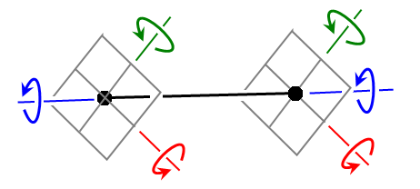
Figure 1: Coupling Rotations at Actuator Ends
By default, the connections between the actuator element (black) and structure (gray) behave like ball joints; the structure at each end can rotate in all three directions independent of each other. If the Couple axial rotations of two ends of element option is activated, then a torque is transmitted through the actuator so that the axial rotation angle (blue arrows) of the structures attached to each end is identical. If the Couple planar rotations of two ends of element option is activated, then a moment is applied at each end of the actuator so that the perpendicular rotation angles (green and red arrows) of the structure attached to the actuator are identical.
Naturally, the rotations of the structure attached to the actuator can be controlled only if the elements of the structure have rotational degrees of freedom, such as beam and shell elements.
Advanced Actuator Element Parameters
You can control how often the actuator geometry is updated. The geometry will always be updated after each converged time step. For the geometry to be updated after each iteration in a time step, select the Previous iteration option in the Geometric update based on drop-down box in the Advanced tab of the Element Definition dialog.
Basic Steps for Use of Actuator Elements
- Be sure that a unit system is defined.
- Be sure that the model is using a nonlinear analysis type.
- Right-click the Element Type heading for the part that you want to be actuator elements.
- Select the Actuator command.
- Right-click the Element Definition heading.
- Select the Edit Element Definition command.
- Select the type of actuator element that this part will be in the Type of actuation drop-down box.
- Specify the appropriate information in the appropriate tabs depending on the type of actuator element.
- Press the OK button.