A DDAM analysis can be conducted using either of two methods for the DESIGN VALUE FORMULAS and user-specified values for the coefficients in these formulas and for the design values:
- Using the formulae and coefficient values specified in NRL Memorandum Report 1396.
- Using a generalized functional form for the formulae and user-specified coefficient values.
In this document we describe how to conduct a DDAM analysis using user-specified values for the coefficients. These coefficients are read from an ASCII file (with an arbitrary name, but with structure as given in Appendix A). This file can exist anywhere accessible to the user interface. To invoke the use of this file, select the Use user-specified coefficients check-box for the case of an ASCII file with name C:\Algor\Ddam.def.
Generalized Functional Form for DESIGN VALUE FORMULAS
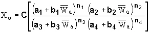
The functional form
 (1)
(1)
is used to describe the reference equations for A 0 and V 0 for all ship type and mounting configurations. The user-specified coefficients are:
C, a 1 , b 1 , n 1 , a 2 , b 2 , n 2 , a 3 , b 3 , n 3 , a 4 , b 4 , n 4 .
A different set of coefficients exists for each ship type and mounting configuration; these are given in the ASCII text file using the notation:
C, a1, b1, n1, a2, b2, n2, a3, b3, n3, a4, b4, n4.
Below are listed the default values for these coefficients; these are the values that the current DDAM processor utilizes. The format used to list these values is that used by the ASCII text file (see the following Note):
Ship Type: Submarine
Mounting Type: Hull Mounted Systems
- A0 Reference Equation Coefficients: C, a1, b1, n1, a2, b2, n2, a3, b3, n3, a4, b4, n4
10.4, 480, 1, 1, 0, 0, 0, 20, 1, 1, 0, 0, 0
- V0 Reference Equation Coefficients: C, a1, b1, n1, a2, b2, n2, a3, b3, n3, a4, b4, n4
20.0, 480, 1, 1, 0, 0, 0, 100, 1, 1, 0, 0, 0
- Design Values: AE1, VE1, AP1, VP1, AR1, VR1
1.0, 1.0, 1.0, 0.5, 0, 0
- Design Values: AE2, VE2, AP2, VP2, AR2, VR2
1.0, 1.0, 1.0, 0.5, 0, 0
- Design Values: AE3, VE3, AP3, VP3, AR3, VR3
0.4, 0.4, 0.4, 0.2, 0, 0
Ship Type: Submarine
Mounting Type: Deck Mounted Systems
- A0 Reference Equation Coefficients: C, a1, b1, n1, a2, b2, n2, a3, b3, n3, a4, b4, n4
5.2, 480, 1, 1, 0, 0, 0, 20, 1, 1, 0, 0, 0
- V0 Reference Equation Coefficients: C, a1, b1, n1, a2, b2, n2, a3, b3, n3, a4, b4, n4
10.0, 480, 1, 1, 0, 0, 0, 100, 1, 1, 0, 0, 0
- Design Values: AE1, VE1, AP1, VP1, AR1, VR1
1.0, 1.0, 1.0, 0.5, 0, 0
- Design Values: AE2, VE2, AP2, VP2, AR2, VR2
2.0, 2.0, 2.0, 1.0, 0, 0
- Design Values: AE3, VE3, AP3, VP3, AR3, VR3
0.8, 0.8, 0.8, 0.4, 0, 0
Ship Type: Submarine
Mounting Type: Shell Plating Mounted Systems
- A0 Reference Equation Coefficients: C, a1, b1, n1, a2, b2, n2, a3, b3, n3, a4, b4, n4
52, 480, 1, 1, 0, 0, 0, 20, 1, 1, 0, 0, 0
- V0 Reference Equation Coefficients: C, a1, b1, n1, a2, b2, n2, a3, b3, n3, a4, b4, n4
100, 480, 1, 1, 0, 0, 0, 100, 1, 1, 0, 0, 0
- Design Values: AE1, VE1, AP1, VP1, AR1, VR1
1.0, 1.0, 0.0, 0.0, 0, 0
- Design Values: AE2, VE2, AP2, VP2, AR2, VR2
0.20, 0.20, 0.0, 0.0, 0, 0
- Design Values: AE3, VE3, AP3, VP3, AR3, VR3
0.08, 0.08, 0.0, 0.0, 0, 0
Ship Type: Surface Ships
Mounting Type: Hull Mounted Systems
- A0 Reference Equation Coefficients: C, a1, b1, n1, a2, b2, n2, a3, b3, n3, a4, b4, n4
20.0, 37.5, 1, 1, 12, 1, 1, 6, 1, 2, 0, 0, 0
- V0 Reference Equation Coefficients: C, a1, b1, n1, a2, b2, n2, a3, b3, n3, a4, b4, n4
60.0, 12, 1, 1, 0, 0, 0, 6, 1, 1, 0, 0, 0
- Design Values: AE1, VE1, AP1, VP1, AR1, VR1
1.0, 1.0, 1.0, 0.5, 0, 0
- Design Values: AE2, VE2, AP2, VP2, AR2, VR2
0.4, 0.4, 0.4, 0.2, 0, 0
- Design Values: AE3, VE3, AP3, VP3, AR3, VR3
0.2, 0.2, 0.2, 0.1, 0, 0
Ship Type: Surface Ships
Mounting Type: Deck Mounted Systems
- A0 Reference Equation Coefficients: C, a1, b1, n1, a2, b2, n2, a3, b3, n3, a4, b4, n4
10.0, 37.5, 1, 1, 12, 1, 1, 6, 1, 2, 0, 0, 0
- V0 Reference Equation Coefficients: C, a1, b1, n1, a2, b2, n2, a3, b3, n3, a4, b4, n4
30.0, 12, 1, 1, 0, 0, 0, 6, 1, 1, 0, 0, 0
- Design Values: AE1, VE1, AP1, VP1, AR1, VR1
1.0, 1.0, 1.0, 0.5, 0, 0
- Design Values: AE2, VE2, AP2, VP2, AR2, VR2
0.4, 0.4, 0.4, 0.2, 0, 0
- Design Values: AE3, VE3, AP3, VP3, AR3, VR3
0.4, 0.4, 0.4, 0.2, 0, 0
Ship Type: Surface Ships
Mounting Type: Shell Plating Mounted Systems
- A0 Reference Equation Coefficients: C, a1, b1, n1, a2, b2, n2, a3, b3, n3, a4, b4, n4
40.0, 37.5, 1, 1, 12, 1, 1, 6, 1, 2, 0, 0, 0
- V0 Reference Equation Coefficients: C, a1, b1, n1, a2, b2, n2, a3, b3, n3, a4, b4, n4
120.0, 12, 1, 1, 0, 0, 0, 6, 1, 1, 0, 0, 0
- Design Values: AE1, VE1, AP1, VP1, AR1, VR1
1.0, 1.0, 0.0, 0.0, 0, 0
- Design Values: AE2, VE2, AP2, VP2, AR2, VR2
0.20, 0.20, 0.0, 0.0, 0, 0
- Design Values: AE3, VE3, AP3, VP3, AR3, VR3
0.1, 0.1, 0.0, 0.0, 0, 0
- Multipliers of A0 begin with the letter A
- Multipliers of V0 begin with the letter V
- Elastic have E as their second letter
- Elastic-plastic have P as their second letter
- Reduced elastic have R as their second letter
- Vertical or Normal to Hull have 1 as the last character
- Athwartship or Tangential have 2 as the last character
- Fore and Aft has 3 as the last character
Design Values are used to multiply A0 and V0 depending on shock direction and material. The following notation is used:
APPENDIX A
The structure of the ASCII text files is given below. This file can have any name or extension. It must be structured as described here:
- The 1.00 on the second line; this is the version number for this file reading capability.
- Each set of coefficients must be listed and be listed in the order specified.
- A comment line is recognized by its first character: it must be either '*' or ';', otherwise the line is read as a data line. A comment line can be put anywhere in the data file; DDAM ignores the entire line.
- A blank line is taken as a data line with all zeroes.
- A number is recognized as a string starting with any of the following characters: numbers, signs (+ or -), or decimal point.
- A number string must end with one of following characters: comma, space, and endOFline/endOFfile; anything else is an invalid input.
- A number string only contains characters used by a floating number and follows the usual format for a floating number; for example: 1.0, -1.0E-20, and +1.0D-30 and so on. Anything else is an invalid input.
- Any invalid input will result in a terminal error.
- A data line can contain a maximum of 130 characters.
- If a line contains fewer entries than expected/specified, zero values are used for the missing entries. This will not affect the reading of the following data line.
- If a line contains more entries than expected/specifies, the trailing values are ignored. This will not affect the reading of the following data line.
- If the file does not contain the expected/specified number of data lines, all expected entries are treated as zero.
- If the file contains more than the expected/specified number of data lines, all trailing lines are ignored.
Sample ASCII File
This data corresponds to that specified in NRL Memorandum Report 1396. Note how there is no data is available for the reduced-elastic material case.
*** DDAM: File of User-Defined Coefficients
1.00
****************************************************************
*** GENERAL FILE STRUCTURE
*** Comment lines are preceded by an asterisk (*).
***
*** This file allows users to define the constants used by the
*** DDAM analysis. These constants are either part of a specified
*** functional form, or multiplicative design values.
***
*** All equations have the following functional form
*** X0 = C [ (a1+b1*Wa)**n1 * (a2+b2*Wa)**n2 ] /
*** [ (a3+b3*Wa)**n3 * (a4+b4*Wa)**n4 ]
*** where X0 can be either A0 or V0 in the Design Value Formulas
*** of the DDAM, and Wa is the modal weight.
***
*** Design values are used to multiply A0 and V0 depending on
*** shock direction and material.
*** The following notation is used:
*** - Multipliers of A0 begin with the letter A
*** - Multipliers of V0 begin with the letter V
*** - Elastic have E as their second letter
*** - Elastic-plastic have P as their second letter
*** - Reduced elastic have R as their second letter
*** - Vertical or Normal to Hull have 1 as the last character
*** - Athwartship or Tangential have 2 as the last character
*** - Fore and Aft has 3 as the last character
***
****************************************************************
***
*** SUBMARINES
***
*** Hull Mounted Systems
*** A0 Reference Equation Coefficients:
*** C, a1, b1, n1, a2, b2, n2, a3, b3, n3, a4, b4, n4
10.4, 480, 1, 1, 0, 0, 0, 20, 1, 1, 0, 0, 0
*** V0 Reference Equation Coefficients:
*** C, a1, b1, n1, a2, b2, n2, a3, b3, n3, a4, b4, n4
20.0, 480, 1, 1, 0, 0, 0, 100, 1, 1, 0, 0, 0
*** Design Values:
*** AE1, VE1, AP1, VP1, AR1, VR1,
1.0, 1.0, 1.0, 0.5, 0.0, 0.0
*** AE2, VE2, AP2, VP2, AR2, VR2,
1.0, 1.0, 1.0, 0.5, 0.0, 0.0
*** AE3, VE3, AP3, VP3, AR3, VR3,
0.4, 0.4, 0.4, 0.2, 0.0, 0.0
***
*** Deck Mounted Systems
*** A0 Reference Equation Coefficients:
*** C, a1, b1, n1, a2, b2, n2, a3, b3, n3, a4, b4, n4
5.2, 480, 1, 1, 0, 0, 0, 20, 1, 1, 0, 0, 0
*** V0 Reference Equation Coefficients:
*** C, a1, b1, n1, a2, b2, n2, a3, b3, n3, a4, b4, n4
10.0, 480, 1, 1, 0, 0, 0, 100, 1, 1, 0, 0, 0
*** Design Values:
*** AE1, VE1, AP1, VP1, AR1, VR1,
1.0, 1.0, 1.0, 0.5, 0.0, 0.0
*** AE2, VE2, AP2, VP2, AR2, VR2,
2.0, 2.0, 2.0, 1.0, 0.0, 0.0
*** AE3, VE3, AP3, VP3, AR3, VR3,
0.8, 0.8, 0.8, 0.4, 0.0, 0.0
***
*** Shell Plating Mounted Systems
*** A0 Reference Equation Coefficients:
*** C, a1, b1, n1, a2, b2, n2, a3, b3, n3, a4, b4, n4
52, 480, 1, 1, 0, 0, 0, 20, 1, 1, 0, 0, 0
*** V0 Reference Equation Coefficients:
*** C, a1, b1, n1, a2, b2, n2, a3, b3, n3, a4, b4, n4
100, 480, 1, 1, 0, 0, 0, 100, 1, 1, 0, 0, 0
*** Design Values:
*** AE1, VE1, AP1, VP1, AR1, VR1
1.0, 1.0, 0.0, 0.0, 0.0, 0.0
*** AE2, VE2, AP2, VP2, AR2, VR2
0.2, 0.2, 0.0, 0.0, 0.0, 0.0
*** AE3, VE3, AP3, VP3, AR3, VR3
0.08, 0.08, 0.0, 0.0, 0.0, 0.0
***
****************************************************************
***
*** SURFACE SHIPS
***
*** Hull Mounted Systems
*** A0 Reference Equation Coefficients:
*** C, a1, b1, n1, a2, b2, n2, a3, b3, n3, a4, b4, n4
20.0, 37.5, 1, 1, 12, 1, 1, 6, 1, 2, 0, 0, 0
*** V0 Reference Equation Coefficients:
*** C, a1, b1, n1, a2, b2, n2, a3, b3, n3, a4, b4, n4
60.0, 12, 1, 1, 0, 0, 0, 6, 1, 1, 0, 0, 0
*** Design Values:
*** AE1, VE1, AP1, VP1, AR1, VR1
1.0, 1.0, 1.0, 0.5, 0.0, 0.0
*** AE2, VE2, AP2, VP2, AR2, VR2
0.4, 0.4, 0.4, 0.2, 0.0, 0.0
*** AE3, VE3, AP3, VP3, AR3, VR3
0.2, 0.2, 0.2, 0.1, 0.0, 0.0
***
*** Deck Mounted Systems
*** A0 Reference Equation Coefficients:
*** C, a1, b1, n1, a2, b2, n2, a3, b3, n3, a4, b4, n4
10.0, 37.5, 1, 1, 12, 1, 1, 6, 1, 2, 0, 0, 0
*** V0 Reference Equation Coefficients:
*** C, a1, b1, n1, a2, b2, n2, a3, b3, n3, a4, b4, n4
30.0, 12, 1, 1, 0, 0, 0, 6, 1, 1, 0, 0, 0
*** Design Values:
*** AE1, VE1, AP1, VP1, AR1, VR1
1.0, 1.0, 1.0, 0.5, 0.0, 0.0
*** AE2, VE2, AP2, VP2, AR2, VR2
0.4, 0.4, 0.4, 0.2, 0.0, 0.0
*** AE3, VE3, AP3, VP3, AR3, VR3
0.4, 0.4, 0.4, 0.2, 0.0, 0.0
***
*** Shell Plating Mounted Systems
*** A0 Reference Equation Coefficients:
*** C, a1, b1, n1, a2, b2, n2, a3, b3, n3, a4, b4, n4
40.0, 37.5, 1, 1, 12, 1, 1, 6, 1, 2, 0, 0, 0
*** V0 Reference Equation Coefficients:
*** C, a1, b1, n1, a2, b2, n2, a3, b3, n3, a4, b4, n4
120.0, 12, 1, 1, 0, 0, 0, 6, 1, 1, 0, 0, 0
*** Design Values:
*** AE1, VE1, AP1, VP1, AR1, VR1
1.0, 1.0, 0.0, 0.0, 0.0, 0.0
*** AE2, VE2, AP2, VP2, AR2, VR2
0.2, 0.2, 0.0, 0.0, 0.0, 0.0
*** AE3, VE3, AP3, VP3, AR3, VR3
0.1, 0.1, 0.0, 0.0, 0.0, 0.0
***
*** Cut-Off Value:
2316.0