Parts, layers, and surfaces are often just a modeling convenience when you model for CAD or visualization purposes. As you will notice, each entity (lines, splines, arcs, and so on) has a surface, layer and part property associated with it. Every item displayed will have three properties. To view the different properties, you can use the View Appearance Color By drop-down menu. In the drop-down menu you will see the Part, Surface, Layer and Edge commands.
If you are modeling for finite element analysis, surface and part properties are used by the software to indicate various properties.
Surfaces
Surfaces in your model are used to assign surface loads such as applied pressure, convection, or radiation to specific elements.
- For 2D elements, the edge with the highest surface number among the three or four sides of the element determines the surface property of the element. This edge becomes the ij edge where pressures are applied. Positive pressure points into the element while negative pressure points away from the element.
- For 3D plate and membrane elements not created from a CAD solid model, the highest surface number among any sides of the element defines the surface property of the element. For plate elements created from a CAD solid model, the surface of the CAD solid model will define the surface of the plate elements. The pressure is applied so that a positive pressure will try to move the element away from the defined element normal point.
- 4, 5, 6 and 8-node brick elements. If the model originated from a CAD solid model, all faces coincident with the surface of the CAD model have the corresponding surface number. Thus, those faces will receive the load regardless of the surface number of the lines. In hand-built models and on CAD parts that are altered so that the part is no longer associated with the CAD part, the surface number that is common in any three of the four lines that define a face (four-node region) or two of the three lines (three-node region) determines the surface number of that face.
Parts
Parts in your model are used to assign different materials and element types to specific elements. To combine different element types, such as plates with beams, simply put the different elements into unique part numbers.
Layers
Layers are generally used for graphical filtering when building models. Use layers to group sections of a complex model so that you can hide portions of the model (Draw Design Layer Control) while working on other sections.
The only elements that have properties associated with the layer property are beams. The layer property for beams controls the sectional properties associated with the beam element. If you need to model different cross sections for beams, then you need to put the beams into unique layers.
Use multiple parts when modeling
You should change the part number whenever a part of your model is of a different material and/or when you have multiple element types or element properties (such as thickness) in the model. If you have aluminum and steel in the model, you need two parts in the model. Also, if you are modeling a structure with beam elements and plate elements, you need two parts in the model. Finally, each part in the model must consist of complete elements. Therefore, at the interface of different part numbers you need the lines to be defined in both of the parts meeting at that location.
For example, you have elements of Part 1 and Part 2 that meet as shown here:
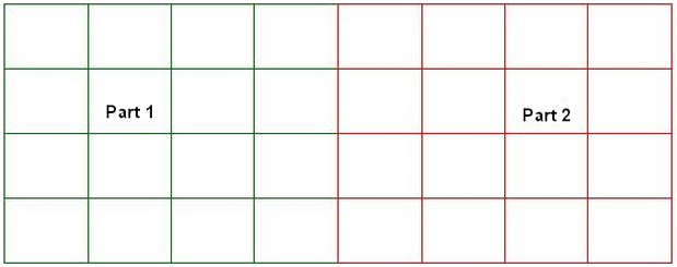
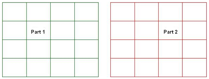
It appears that the interface only consists of Part 2 lines. However, if we separate the two parts (as shown below), we see that each part has lines at the interface as desired. This is exactly how the interface of different part numbers should be modeled so that we have complete elements for Part 1 and Part 2.