Nonlinear beam elements can output results to three different ASCII text files depending on the options chosen under the Element Definition. (See the previous topic, Beam Elements: Advanced Beam Element Parameters.)
Forces and Moments
When Detailed force and moment output is activated, the forces and moments in the beam element part are written to the summary file (.AL). The format of this text file is as follows:
Elem Node Force-1 Force-2 Force-3 Torque-1 Moment-2 Moment-3
where
- Elem is the element number. Each part begins with element number 1.
- Node is the local element node. Node 1 is the i node and node 2 is the j node.
- Force-1 is the axial force in the direction of axis 1
- Force-2 is the shear force in the direction of axis 2
- Force-3 is the shear force in the direction of axis 3
- Torque-1 is the torque (moment) about axis 1
- Moment-2 is the moment about axis 2
- Moment-3 is the moment about axis 3
If material does not undergo any nonlinear behavior (such as plasticity) and user knows the location of the neutral axis, the stress can be simply calculated from given geometry, force and moment data. However, if material experiences yield or nonlinear behavior, stress can’t be simply calculated from these. In such situations, use the stress (or strain) output.
Stress and Strain
When either Detailed stress output or Detailed strain output is activated, the stresses and strains in the beam element part are written to the beam stress output (.BSO) and beam strain output (.BST) files, respectively. The format of these text files is identical and is as follows:
Element Axial-Int Sec# Int2 Int3 State Stress-11 Stress-12 Stress-13
or
Element Axial-Int Sec# Int2 Int3 State Strain-11 Strain-12 Strain-13
where
- Element is the element number
- Axial-Int is the integration point in axial direction (1 axis) and increments from 1 through the integration order set by the user (7 maximum)
- Sec# is the section number (when cross section is treated as a series of rectangles)
- Int2 is the integration point in local y-dir (2 axis) and increments from 1 through the integration order set by the user (7 maximum)
- Int3 is the integration point in local z-dir (3 axis) and increments from 1 through the integration order set by the user (7 maximum)
- State indicates whether the point is elastic or plastic
- Stress-11 is the normal stress in the 11 direction
- Stress-12 is the shear stress in the 12 direction
- Stress-13 is the shear stress in the 13 direction
- Strain-11 is the normal strain in the 11 direction
- Strain-12 is the shear strain in the 12 direction
- Strain-13 is the shear strain in the 13 direction
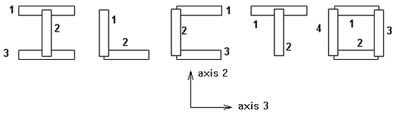
Imagine the beam element composed of numerous integration points in all three directions (axis 1 along the length, axes 2 and 3 in the plane of the cross section). The stress output is given at all the integration points, so with the integration order set to 2x2x2, each element would output 8 lines of stresses for each element.
Find the 3D position (X, Y, Z) of the integration point (Int1, Int2, Int3) within the element. This is done with the following calculations depending on the shape.
Rectangle
Y = C(Int2,INTy)*height*0.5, measured from the neutral axis in the direction of axis 2
Z = C(Int3,INTz)*width*0.5, measured from the neutral axis in the direction of axis 3
Circle
R = radius/2
R = R + C(Int2,INTy)*R
α = (2π/INTz)*(Int3-1)
Y = R*cosα , measured from the neutral axis in the direction of axis 2
Z = R*sinα , measured from the neutral axis in the direction of axis 3
Hollow circle
R = (Ro+Ri)/2
R = R + C(Int2,INTy)*(Ro-Ri)/2
α = (2π/INTz)*(Int3-1)
Y = R*cos(α), measured from the neutral axis in the direction of axis 2
Z = R*sin(α), measured from the neutral axis in the direction of axis 3
where
- X = C(Axial-Int,INTx)*0.5*Length+0.5*Length, measured from node i (= node 1)
- INTx is the total number of integration points in x-dir (Integration Order in local 1 axis)
- INTy is the total number of integration points in y-dir (Integration Order in local 2 axis)
- INTz is the total number of integration points in z-dir (Integration Order in local 3 axis)
and the quantity C(i, Integration Order) is from the following table:
| Integration Order | C(i, Integration Order) | ||||||
|---|---|---|---|---|---|---|---|
| i = 1 | i = 2 | i = 3 | i = 4 | i = 5 | i = 6 | i = 7 | |
| 1 | 0 | - | - | - | - | - | - |
| 2 | -1 | 1 | - | - | - | - | - |
| 3 | -1 | 0 | 1 | - | - | - | - |
| 4 | -1 | -0.333 | 0.333 | 1 | - | - | - |
| 5 | -1 | -0.5 | 0 | 0.5 | 1 | - | - |
| 6 | -1 | -0.6 | -0.2 | 0.2 | 0.6 | 1 | - |
| 7 | -1 | -0.666 | -0.333 | 0 | 0.333 | 0.666 | 1 |
General cross section
Each section is treated as an independent quadrangle separately. C(i,j) can be directly applied to find the position.
Predefined cross section
Each section is treated like an independent quadrangle separately as below, with the section number indicated.