On the Job Preferences dialog, you can define parameters for a story plan for a structural project.
Use the tabs on the dialog to define parameters:
Definition tab - define a story plan type
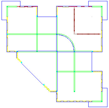
- Story plan according to the model representation - top view
For this plan type, the created drawing will include all visible elements of a structure model, as well as colors, hatching styles, and other parameters assigned to elements, as shown below.
Only the Definition and General parameters tabs are available for this plan type:
a) Definition tab
If you select Draw symbolic elements of a higher story, the story plan drawing will display structure elements situated on a higher story. You can specify style, color, and thickness for the edges of the element outline.
b) General parameters tab
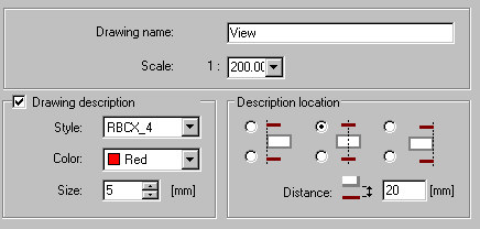
- Specify a drawing name and scale.
- Drawing description - select this in order to specify Style, Color, and Size.
- Description location - define the location of a description in a foundation plan drawing and a distance between the description and the view drawing.
Note: If you select Drawing description, the defined drawing name will be included in the Object Inspector dialog and in the created drawing (as a drawing title). If you clear Drawing description, the defined drawing name will be included only in the Object Inspector dialog. - Story plan as a regular horizontal section (illustrated below)
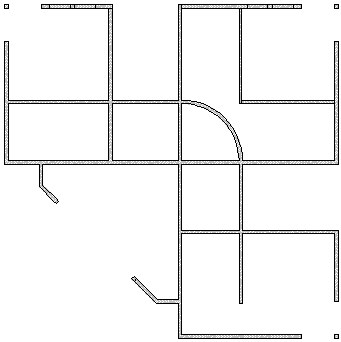
Use the tabs on the dialog to define parameters:
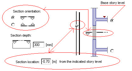
a) Definition tab - define the parameters of the horizontal plan of a structure model
- Base story level
- Section orientation
- Section depth
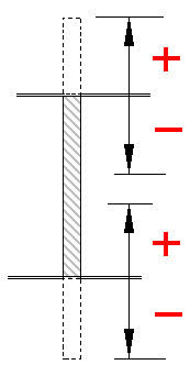
- Section location - with respect to a selected story level (it can be defined by means of the slider or by entering a number in edit field. The sign convention for values of the section location is as shown.
Example parameters of the horizontal section
Base story level = upper
Section orientation = down
Section depth = 30 cm
Section location = 70 cm from the upper story level
b) General parameters tab
- Specify a drawing name and scale.
- Drawing description - select this in order to specify Style, Color, and Size.
- Description location - define the location of a description in a foundation plan drawing and a distance between the description and the view drawing.
Note: If you select Drawing description, the defined drawing name will be included in the Object Inspector dialog and in the created drawing (as a drawing title). If you clear Drawing description, the defined drawing name will be included only in the Object Inspector dialog.For a classic story plan, if you select Present openings/recesses independently of the cutting level - projection, openings/recesses are included in the story plan regardless of the selected cutting level. All openings/recesses are projected onto one common level. This option is particularly useful if you need to show all wall openings (usually positioned on different levels) in one plan.
c) Visible elements tab - define parameters for contour edges and hatching
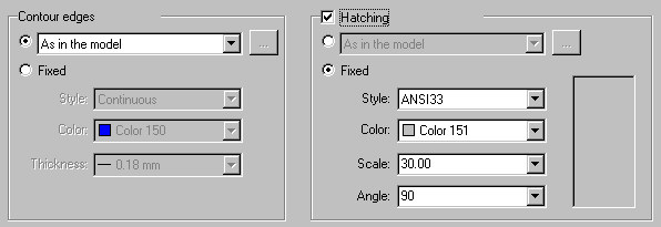
- As in the model / By element type / By material (available for Hatching only)
- Fixed - lets you specify parameters
o Contour edges - line style, color, and thickness
o Hatching - style, color, scale, and angle
d) Cut elements tab - use the options on this tab (which are the same as those on the Visible elements tab) to define the display of cut elements in a story plan.
e) Invisible elements tab - use the options on this tab (which are the same as those on the Visible elements tab) to define the display of invisible elements in a story plan.
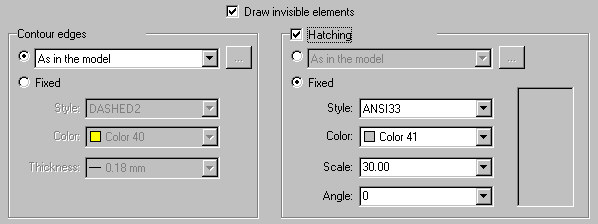
Invisible elements are displayed in the story plan if the Draw invisible elements option is selected.
See also: