The Positions tab displays a list of user-defined positions (defined using the Positioning option), which is sorted by prefixes and numbers.
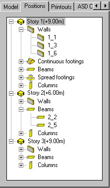
Positions are displayed with 1 of 2 icons:
 - this icon designates a position that has a formwork drawing in the same project as a structure model (an Autodesk AutoCAD Structural Detailing - Formwork Drawings project).
  - this icon designates a position that has a formwork drawing created in Autodesk AutoCAD Structural Detailing - Reinforcement. This drawing is saved in a separate file. Double-clicking this icon automatically launches Autodesk AutoCAD Structural Detailing - Reinforcement, and opens the formwork drawing of the selected position.
The context menu that displays when you right-click a selection on the Positions tab depends on what you select: a group of positions (such as walls of a selected story), or a single position.
Context menu for a group of positions
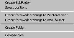
Options for a selected a group of positions:
- Create SubFolder - select this to be able to create an additional subfolder in the position tree
- Select positions - select this command to select a position
- Export formwork drawings to Autodesk AutoCAD Structural Detailing - Reinforcement program- select this command to be able to read the formwork drawings using the Autodesk AutoCAD Structural Detailing - Reinforcement program; The opened dialog Formwork drawing wizard where the drawing items can be selected and the file where the information will be saved can be indicated (see Formwork drawing wizard description)
-
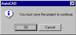
Note: To perform this operation, a project must be saved in a file with a specified name; if the project is not saved, the message shown in the drawing below appears on the screen.
- Export formwork drawings to DWG - selecting this command allows saving formwork drawings in a *.DWG format file; the dialog Formwork drawing wizard is opened where the drawing items can be selected and the file where the information will be saved can be indicated (see Formwork drawing wizard description)
- Create Folder - select this to be able to create an additional folder in the position tree.
Context menu for a single position
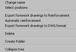
Options for a selected position:
- Modify name - select this to be able to modify the name of a selected position; type the new position name on the command line.
- Select positions - select this to be able to specify positions.
- Export formwork drawings to Autodesk AutoCAD Structural Detailing - Reinforcement - select this to be able to read formwork drawings by Autodesk AutoCAD Structural Detailing - Reinforcement. The software opens the Formwork drawing wizard, where you can select drawing positions and indicate a file in which to save information (see the description of the Formwork drawing wizard). Note: To perform this operation, a project must be saved in a file with a specified name. If the project is not saved, a warning message displays.
- Automatic reinforcement - select this to be able to automatically generate reinforcement for a selected position in Autodesk AutoCAD Structural Detailing - Reinforcement.
- Export formwork drawings to DWG format - select this to be able to save formwork drawings in a *.DWG format file. The Formwork drawing wizard opens, where you can select drawing positions and indicate a file to which to save information (see the description of the Formwork drawing wizard).
- Delete - select this to delete a selected position.
- Create Folder - select this to be able to create an additional folder in the position tree.
Note: The options allowing export of formwork drawings and automatic reinforcement are available after building elements have been positioned.
Options for structure plans / views (story plan, foundation plan, elevation view, section through a structure, 3D view):
- Activate - select this to activate a specified drawing.
- Add to current printout - selecting this command adds a view with selected drawing to the current printout
- Add to current printout - selecting this command adds a view with selected drawing in form of block to the current printout .
- After activating the command, the user can see the preview of the inserted drawing and indicates the graphic location of the drawing on the layout. It is assumed that independent of the current drawing view in the Edition Layout (e.g. the drawing is shifted, moved away, etc.) the block insertion point with the drawing will be located as close to the drawing as possible (bottom left corner) in order to facilitate the drawing location in the printout layout. The context menu is available for the inserted block with a drawing. The user can start editing the drawing from its level. It activates the Edition Layout where the user can introduce changes to the drawing. The changes are automatically taken in consideration in the drawing printout.
- Update - select this to update a selected drawing (after changes made in a structure model).
- Properties - select this to open the Modification of parameters for drawings dialog for a given plan / view of a structure.
- Hide objects - select this to hide some of the objects (section symbols and axes) in structure plans / views.
- Show all hidden objects - select this to restore the display of hidden objects (section symbols and axes) in structure plans / views.
- Layers - select this to open the Layers dialog.