By default, the Object Inspector dialog is located to the left of the drawing area. You can adjust the width of the dialog in order to leave as much space as possible for the drawing area, where you define a structure model.
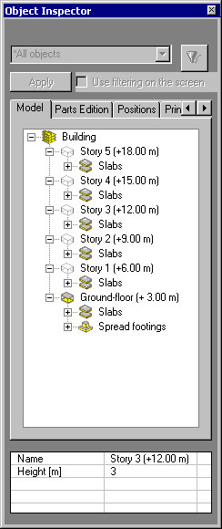
The Object Inspector dialog contains:
- Tabs that display lists (sets) of project elements depending on the design stage (modeling / positions / printouts)
- Model
- Parts Edition
- Positions
- Printouts
- ASD Center
- A table that displays properties of selected objects.
Each of the tabs is intended for displaying elements in different stages of a design process. Therefore, each tab comprises different types of objects organized in a slightly different way.
In the table at the bottom of the dialog:
- If a single element is selected, the table displays all properties of the selected element
- If several objects of the same type are selected, the table displays all the fields with properties relevant to the selected element type. However, only the values that are common for all the elements display; the remaining fields are blank (but may be changed)
- If several objects of different types are selected, the table displays only the fields with properties that are common for all object types.