The following example illustrates the definition of point reinforcement in the cross section of the beam. For definition of the beam contours the Formworks - Beam macro has been used.
To define point reinforcement in the beam:
- Define transversal and longitudinal reinforcement
DEFINITION OF THE BEAM FORMWORK
- Run the Formworks - Beam macro by clicking
 .
. - In the Formworks - Beam dialog, specify the following parameters:
- section type: 1 (rectangular)
- beam type: 1 (single-span beam)
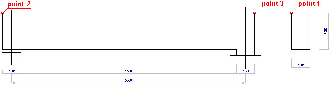
- dimensions of the beam cross section: height = 600 mm, width = 300 mm
- beam geometry displays as follows:

- Click Insert in the Formworks - Beam dialog.
- Indicate the location of the beam formwork in the drawing.
DEFINITION OF THE BEAM REINFORCEMENT
- Click the Reinforcement - cross-section icon

- In the Reinforcement - cross-section dialog, specify the following parameters:
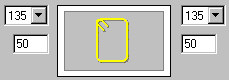
- type of reinforcing bars: polygon-shaped (closed) stirrup

- bar diameter: 8 mm; cover of reinforcing bars: 30 mm
- steel grade: R
- shape parameters as shown in the drawing below
- type of reinforcing bars: polygon-shaped (closed) stirrup
- Click
 (Pick point).
 - In the drawing of the beam formwork indicate a point within the beam cross section and point 1 that determines the position of stirrup hooks.
- Accept the deafult reinforcement description proposed in the Reinforcement description dialog by clicking OK.
- Indicate the position of the reinforcement description in the drawing by clicking Enter, or right-clicking the Enter option from the context menu.
Define the straight longitudinal reinforcement (with the reinforcement in the beam cross section already defined), as follows:
- Click the Reinforcement - elevation icon

- In the Reinforcement - elevation dialog, specify the following parameters:
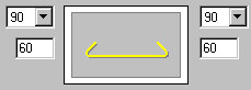
- type of reinforcing bars: straight bar

- bar diameter: 12 mm; cover of reinforcing bars: 30 mm
- steel grade: R
- shape parameters as shown below
- type of reinforcing bars: straight bar
- Click
 (2 points).
 - In the drawing of the beam formwork, indicate point 2 and point 3.
- Accept the deafult reinforcement description proposed in the Reinforcement description dialog by clicking OK.
- Indicate the position of the reinforcement description in the drawing by clicking Enter or right-click the Enter option from the context menu.
Once the transversal and longitudinal reinforcement is defined, define the point reinforcement as follows:
- Click the Reinforcement - point icon

- Indicate the defined longitudinal bar.
- Specify the following parameters; bar distribution: regular

- Click
 (Whole segment), indicate the upper part of the defined stirrup, and click Enter.
 - Specify the following parameters:
- number of bars n = 3
- leave default values of the remaining parameters
- Click OK.
- Adopt the following parameters of the description of reinforcement distribution:
- type of reinforcing bar representation: all

- position: the Active option switched on
- type of distribution description:

- type of reinforcing bar representation: all
- Click OK.
- Indicate the position of the reinforcement description in the drawing by clicking Enter or right-clicking the Enter option from the context menu.
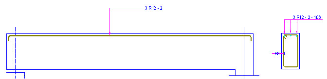
The defined point reinforcement is presented in red in the drawing below: