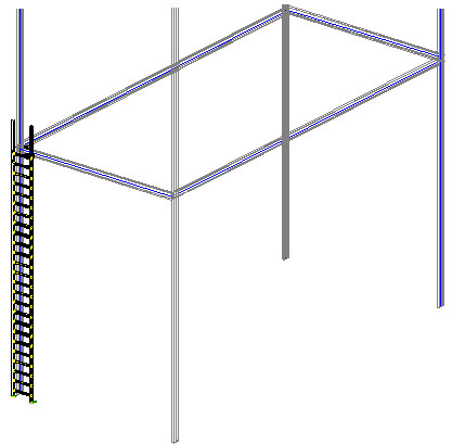
Note: A ladder has been defined in the 3D frame presented in the drawing below.
To define a ladder:
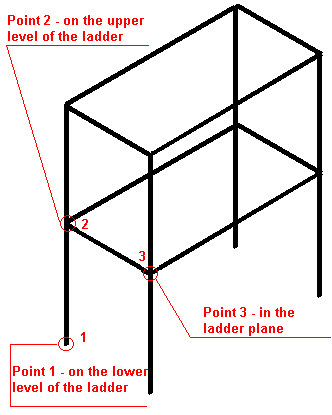
- Define a 3D frame as displayed in the drawing above.
- Click the option Ladder
 .
. - In the drawing area, click to specify 3 points defining the ladder location (P1, P2, and P3 as shown above).
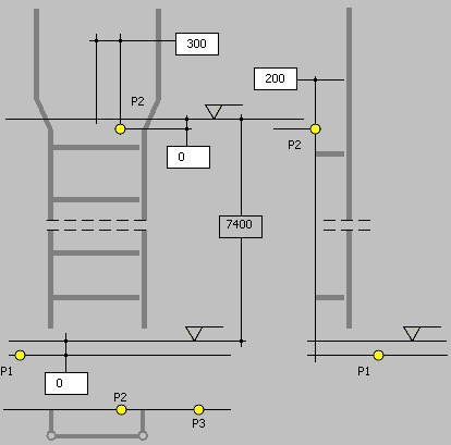
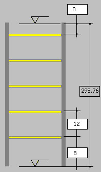
- On the Position tab of the Ladders dialog, specify the ladder dimensions as shown below:
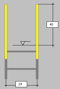
- On the Vertical bars tab, specify parameters:
- For Type of extended bars, select Direct.
- For Profiles, select LP 3.5x3.5x0.25.
- For Families, select Profile.
- For Materials, select STEEL.
- Enter dimensions as shown below:
- On the Rungs tab, specify parameters:
- For Rung connections, select Simple.
- For Profiles, select C 3x6.
- For Families, select Profile.
- For Materials, select STEEL.
- Enter dimensions as shown below:
- On the Connections tab, select Ladder base on the lower level (the ladder will be connected to the lower floor level). When an additional connection to the lower level is added to the list of connections, highlight it, click Properties, and then click OK to accept the default connection values in the Connection properties dialog.
- At the bottom of the dialog, specify bolt parameters:
- Bolt diameter = 0.625
- Grade = 4.8
- Click Save as template (an additional dialog displays, in which the template name is specified, and the settings will be saved to an external file). After you reopen the dialog for ladder definition, this template will be available for use.
- Click OK. The defined ladder is generated at the selected location in the 3D frame, as shown below.