This table presents edit operations performed on an element (e.g. cuttings, drills) as well as the contents of assemblies and groups. An element (or several elements) currently selected is presented in the form of a tree.
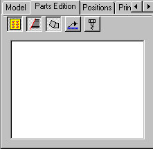
Once the Apply button is clicked, selected objects are shown on the list. If a group is selected, then the group structure is displayed. If a single element is selected, then edit operations carried out on this element are presented.
The manner of presentation are changed by applying the following context menu options: Show hierarchy of: Groups or Connections.
The following object types can be presented in the tree:
- Groups
- Connections
- Profiles
- Plates
- Subparts
- Drills
- Connectors (bolts, welds)
- Cuttings (fits)
- Notches.
The object types are presented on a list or excluded from the presented objects; the following icons located in the dialog serve this purpose:
![]() - drills
- drills
![]() - cuttings (fits)
- cuttings (fits)
![]() - bent profiles
- bent profiles
![]() ,
, ![]() - connectors (welds, bolts).
- connectors (welds, bolts).
All the listed icons are selected by default.
When elements are selected from the list, they are highlighted in the graphical editor (the selection operation is interactive, all the elements chosen in the Inspector dialog are highlighted in the graphic editor: if an element is selected in the graphic editor, then the selection is also presented in the Inspector dialog).
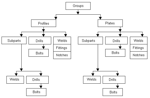
The hierarchy applied to present individual elements is illustrated in the figure below. There is a separate hierarchy for each connection.
The context menu (accessed by right-clicking the Parts Edition tab), includes several options used to perform operations on selected elements:
- Remove - select this command to remove selected elements from a project
- Zoom selection - select this command to zoom-in on the selected elements in a structure view.
- Modify properties - select this command to open the properties dialog (the dialog contents depend on a selected object type); this command is available only when one element is selected on the list
- Assign position - select this command to assign positions to selected elements; activating this command opens the Manual Positioning dialog.
- Remove position - select this command to remove positions from selected elements.