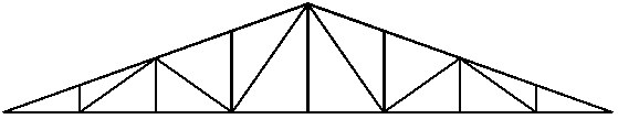
The example below is for creating drawings of a simple truss.
To create a drawing of structure elements:
- On the Model tab of the Object Inspector dialog, select all the truss profiles (the profiles will be highlighted).
- Right-click, and click Auto positioning.
- In the Automatic positioning dialog:
- On the General tab
- For Positioning level, select single part.
- For Prefix, select By family.
- For Number, specify numerical format, start from 1, step = 1.
- On the Additional tab, select all options.
- On the Numbering tab
- For Sort by, select element shape.
- For Sorting criteria, select family.
- On the General tab
- Click Run; all the truss elements will be assigned positions according to the parameters defined in the Automatic positioning dialog.
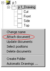
- On the Positions tab of the Object inspector dialog, select the first position p1 (the position will be highlighted).
- Right-click, and click Attach document (see the drawing below).
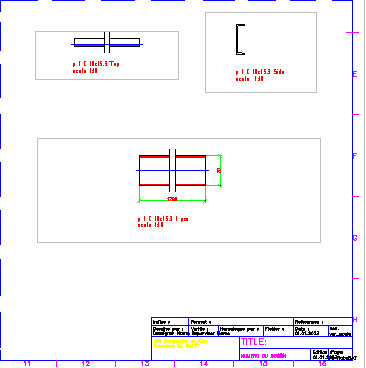
- In the Select template dialog, select the template Profile 1:10 that will be used to create documents (projections), and click OK. In the edition layout, the software has generated projections / views for the selected position.
- On the Printouts tab of the Object Inspector dialog, right-click A1 ASD, and click Activate.
- On the Positions tab, right-click the first position, and click Add to current Printout.
- In the drawing area, click to specify the location of the document (projections of elements) in the printout layout. The selected drawing of the position has been added to A1 ASD on the Printouts tab in the Object Inspector dialog (part of this drawing is shown below).