Positioning will be illustrated using a simple 3D frame generated with the Multispan Frame - Geometry macro available in Autodesk AutoCAD Structural Detailing - Steel. To define a multi-span frame:
- Click the Multispan frame
 option.
 - In the drawing area, click to specify the frame insertion point.
- On the Geometry tab of the Parametric Structures - 3D Frame -Multispan hall dialog:
- For Number of spans, enter 2.
- For Number of frames, enter 2.
- For Frame spacing, enter 8000 mm.
- Select Rafters and External spandrel beams.
- Accept any user-defined dimensions of the frame that display in the dialog.
- Click the Profiles tab, and specify the attributes for component elements of the frame:
- For Columns - select profile C 10 x 15.3 and select family Column.
- For Rafters - select profile C 10 x 15.3 and select family Beam.
- For Spandrel beams - select profile C 10 x 15.3 and select family Beam.
- Click OK. The software will generate a model of the 3D frame.
The profiles generated in the 3D frame have been added on the Model tab of the Object inspector dialog. To assign positions to the elements of the created frame:
- On the Model tab of the Object inspector dialog, select all the profiles, right-click, and click Auto positioning.
- In the Automatic positioning dialog:
- On the General tab, for Positioning level, select single part.
- For Prefix, select By family.
- Under Number, for Format, select Numerical, for Start from, enter 1, and for Step, enter 1.
- On the Additional tab, select all the options.
- On the Numbering tab, for Sort by, select Element shape.
- For Sorting criteria, select Family.
- For Sorting order, select Column and Beam.
- Click Run.
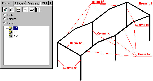
All elements of the 3D frame will be assigned positions according to the parameters specified in the Automatic positioning dialog. Because some frame elements are identical, 3 positions will be created on the Positions tab of the Object inspector dialog: columns c, beams b1, and beams b2. The drawing below illustrates the created positions and location of the structure elements that make up individual positions.
On the Positions tab of the Object inspector dialog, select all the created positions, right-click, and click Automatic Drawings.
- On the Automatic drawing generation dialog:
- On the Templates tab, for Column, select Profile 1:10.
- For Beam, select Profile 1:10.
- On the Formats and scales tab, for Part type, select single profiles
- Select Automatic scale.
- For Format, select A4 ASD.
- For Arrange views, accept the default values.
- On the Options tab, for Names of printouts, select Names consistent with position name.
- For Start printout numbers, select 1.
- Clear all remaining options.
- On the Bill of materials tab, select Add table.
- For Description, select Standard.
- Select Top - Left.
- Click Generate.
Detailed drawings will be generated for all positions (b1, b2, and c1). The software will create additional layouts (b1, b2, and c1), which will display drawings of selected positions. Also, on the Positions tab of the Object Inspector dialog, documents (projections of positions: views and sections) for each position will be added.