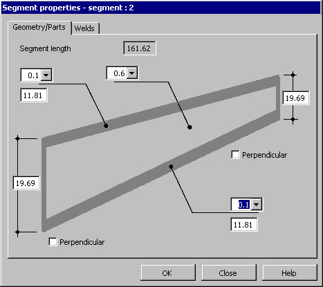
On the Geometry/Parts tab of the Segment properties dialog, you can define the geometry of a selected segment of a multisegment beam.
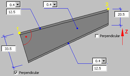
Point 1 is the beginning point of a plate girder segment, and point 2 is the end point of a plate girder segment.
The Segment length field is read-only, because a segment length can be changed only in the Segments table.
A segment of the plate girder (beam) type 2 consists of the following elements: 3 plates (web, upper flange, lower flange) and workshop welds.
Define parameters:
- Thickness and width of the upper flange (these values are constant along the beam length)
- Thickness and width of the lower flange (these values are constant along the beam length)
- Web thickness (this value is constant along the beam length)
- Web height at the beginning and end of the plate girder (the definition method depends on the Perpendicular option)
Define the beginning and end of a beam:
- If you select Perpendicular (at the beginning or end of a beam segment), the web plate and the plate of the lower flange of a beam segment are set in the plane perpendicular to the line defined by points P1 and P2 positioned on the upper flange of a beam. The drawing below displays the Perpendicular option selected at the beginning of the plate girder (at point 1).
- If you don't select Perpendicular (at the beginning or end of a beam segment), edges of the web plate and plates of the beam flanges at the beginning or end of a beam are parallel to the Z axis of the local coordinate system (UCS). The drawing below displays the Perpendicular option switched off at the end of the plate girder (point 2).