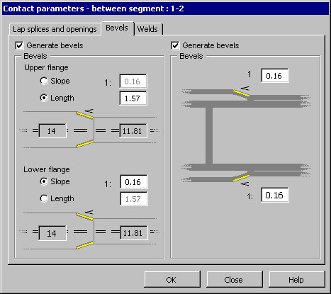
On the Bevels tab of the Contact parameters dialog, you can define parameters of the connection between 2 segments of a multisegment beam (bevels generated for flanges of a plate girder).
For flanges of 2 adjacent segments of different thicknesses and/or widths, you can define bevels of flange plates.
Selecting either of the Generate bevels options lets you define bevels of flanges of a multisegment beam.
Use the options on the right of the dialog to generate bevels for the connection of flange plates of different width (see the drawing below).

After you select Generate bevels on the left of the dialog, you can specify plate bevel parameters for the upper and lower flanges. Bevels are defined symmetrically on both sides of a plate of the flange with the greater width.
Define bevels:
- Specify a value of inclination of the bevel line (for example, 1:4)
- Specify a length of the segment over which a bevel should be generated
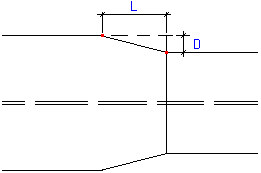
The relationship between the bevel inclination and the segment length is expressed by the formula:
L = X * D /2,
where:
L = length of the bevel segment
D = difference of widths of flanges of adjacent beam segments
X = bevel inclination (for inclination equal to 1:4, the value X = 4)
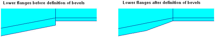
Use the options on the right of the dialog to generate bevels for the connection of flange plates of different thickness.
After you select Generate bevels, you can define plate bevel parameters for the upper and lower flanges by specifying a value of the bevel line inclination (for example, 1:4). The length of a bevel segment is calculated form the same formula given for bevels concerning flange widths. An example of a bevel for the connection of lower flanges (including one inclined) is illustrated in the drawing below.