To insert a detailed description of welds in a drawing use the Insert weld symbol option.
- Menu: Steel > Drawings edition > Insert weld symbol
- Ribbon: ASD - Drawings > Drawings Edition > Insert weld symbol
- Toolbar: Drawings Edition > Insert weld symbol

- Command line: RBCS_ADDWELD.
Welds in drawings can be divided into 2 groups:
- welds defined in a model and presented in a drawing
- welds not defined in a model, only created in a drawing.
Threfore, after selecting the option, the program prompts you to specify if you select a weld from a model or create it manually in a drawing. Then the dialog as shown in the image below displays.
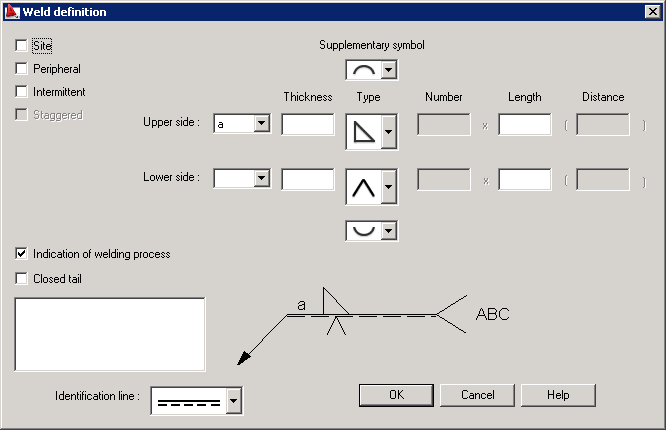
Options in this dialog allow inserting weld symbols and describing welds in drawings according to the requirements of the European codes such as BS, DIN and ISO.
If you are using an imperial template contents of this dialog differs - see the image below.
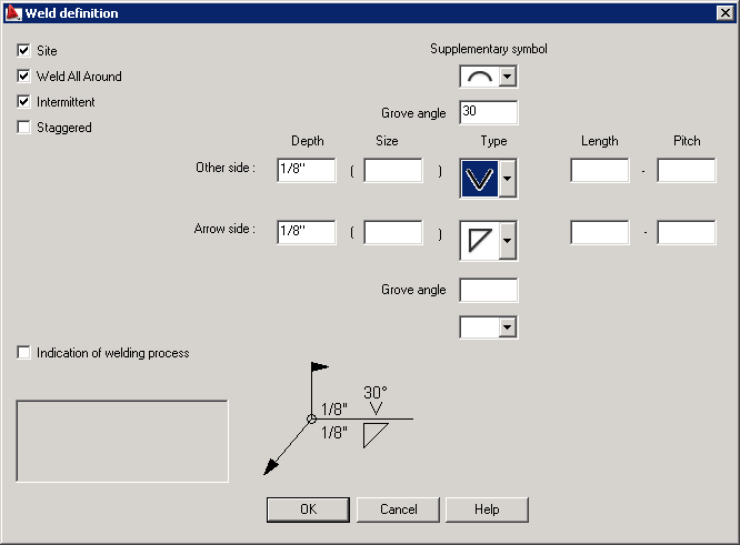
Options in this dialog allow inserting welds symbols and describing welds in drawings according to the requirements of American codes.
If you are opening a file containing a model with welds created using previous versions of the program, a message displays. It prompts you to decide if you want to use the weld mode from the previous version or the weld mode presented above.