Use the Workframe axis dialog to define a new style or modify an existing style of describing workframe axes.
The dialog displays after you click New or Modify in the Styles of descriptions dialog when the Workframe axes category is selected.
Define parameters:
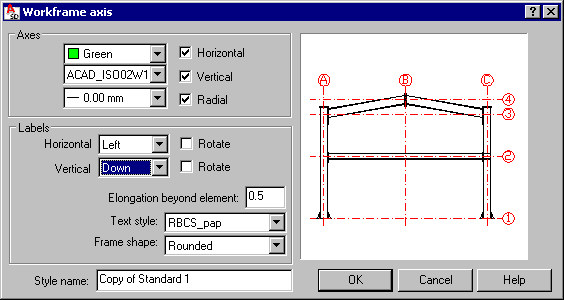
- Under Axes, specify color, style, and line thickness parameters for workframe axes. If Horizontal, Vertical, and Radial are selected, the corresponding workframe axes will be displayed in drawings. If any of the options are not selected, the corresponding axis type will not display in drawings.
- Under Labels, specify description parameters for workframe axes:
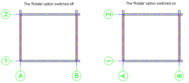
- Vertical - axes may be displayed with labels (above the axis, under the axis, or on both sides) or without labels. If Rotate is selected, axis labels are rotated by 90 degrees (see the drawing below).
- Horizontal - axes may be displayed with labels (on the left side of the axis, on the right side of the axis, or on both sides) or without labels. If Rotate is selected, axis labels are rotated by 90 degrees (see the drawing below).
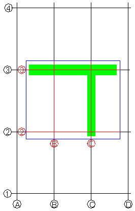
- Elongation beyond element - workframe axes are contained within a rectangular contour, in which a dimensioned group is inscribed. The size of this contour is determined by a rectangle circumscribed on the group contour increased by the value defined in this field (this value is added to each side). Rectangle sides are parallel to view edges, as shown below:
- Green represents an element scheme
- Blue represents element borders with a margin added on each side (a value of elongation beyond element defined in the above dialog)
- Black represents the entire workframe
- Red indicates which part of the workframe will be shown and where labels will be placed
- Text style - select a font to use for workframe description; the list displays all AutoCAD® text styles available in the current project
- Frame shape - select the label shape (rounded, rectangular, or none) for a workframe axis description
- Style name - use this edit field to specify a name for the style