After you have defined the basic parameters of a multisegment plate girder, use the Segments tab to define beam segments.
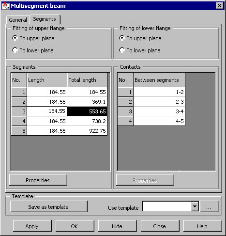
Use the flange options at the top of the dialog to specify parameters for the upper and the lower flanges, if flange thicknesses of successive beam segments differ.
|
to upper plane 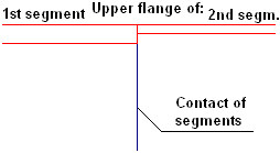 |
to lower plane 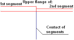 |
Fitting of lower flange
|
to upper plane 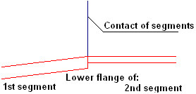 |
to lower plane 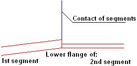 |
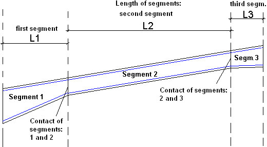
The tables in the central part of the dialog display information about beam segments and contacts (see the drawing below for a beam composed of 3 segments):
- Segments - number of segments, length of individual segments, total length
- Contacts of beam segments - number of segment contacts, which segments are joined with each other
The total beam length equals the distance between the user-defined points P1 and P2. By default, the length of each segment is calculated according to the following formula:
L = distance (P1, P2) / n,
where:
distance (P1, P2) = distance between the user-defined points P1 and P2
n = number of defined segments of a multi-segment beam
To define parameters of an individual segment, select the beam segment in the Segments table and click Properties, which displays the Segment properties dialog.
To define parameters of an individual contact of segments, select the contact in the Contacts table and click Properties, which displays the Contact parameters dialog.