Note: A plate girder (beam) has been defined in the 3D frame, which is in the topic: Example of 3D Frame Definition).
In order to define a plate girder (beam):
- Open the project that contains the defined 3D frame (see Example of 3D Frame Definition).
- Click the Beam option
 .
. - On the Geometry/Parts tab of the Plate girder – beam dialog:
- Select an I-beam
 .
. - Enter the beam dimensions as shown in the drawing below.

- Clear the Perpendicular options at the beginning and at the end of the beam (for points no. 1 and no.2).
- Select an I-beam
- On the Welds tab, for the thickness of welds joining the web with flanges, enter 0.24 in.
- Click Save as template, and enter Plate girder - beam 24/20.5 for the template name. The settings will be saved to an external file, so that you can use the template when defining a plate girder (beam) in the future.
- Click OK.
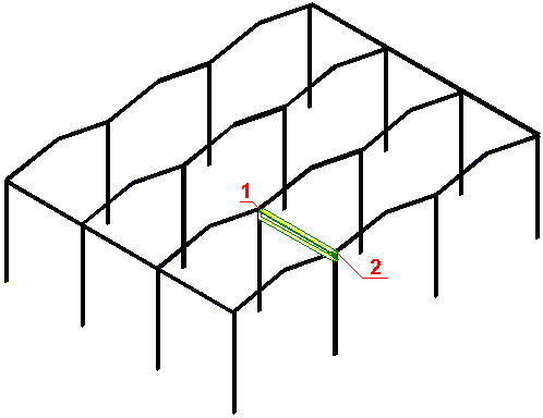
- In the drawing area, click to specify the position of point 1 (the beginning of the plate girder) and point 2 (the end of the plate girder) as shown.
The plate girder generated in the 3D frame is displayed in the drawing below.