Note: Bracings have been defined in the 3D frame (see Example of 3D Frame Definition).
To define bracings in a 3D frame:
- Open a project with a defined frame (see Example of 3D Frame Definition).
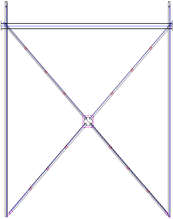
- Draw an auxiliary line of the frame bracing between 2 columns using the AutoCAD® – Draw > Line command (see the drawing below). Because both columns are of equal height, the other diagonal will be a mirror image of the diagonal positioned on the defined auxiliary line.
- Click the Bracing option
 .
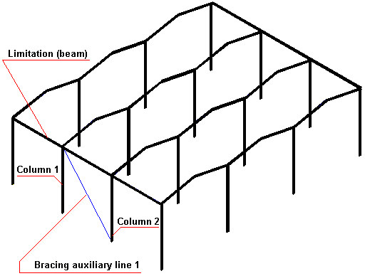
. - In the drawing area, select bracing lines, columns, and objects that define vertical limitations to define the position of frame bracings (see the drawing below).
- On the Gusset plates tab of the Parametric structures - Bracing dialog, specify parameters:
- For Gusset plate type, select Plate.
- Under Gusset plate:
- For Material, select Steel.
- For Family, select Plate.
- For Thickness d, select 0.5 in.
- For Distance, enter 2 in.
- For Plate width, enter 2 in.
- Under Gusset plate position, select Center.
- On the Central plate tab, accept the default values for the plate parameters.
- On the Diagonals tab:
- Select Crossed bracing.
- Under Diagonal selection
- Select profile LP 3.5x3.5x0.25, and family Profile.
- Select Double (double-leg profile of diagonals).
- Select Battens.
- Under Diagonal location in relation to gusset plate
- Select First diagonal in front of the plate.
- For Crossing type, select Both diagonal cut
- For Shortening s, enter 4 in.
- For Diagonal insertion in relation to bracing system line
- Select Middle.
- For Rotation angle, select 0.
- Clear Mirror.
- On the Bolts/Welds tab:
- For Connector type, select Welds.
- Under Welds, for type of welds for gusset plates and profiles, specify 0.12-inch-thick fillet weld.
- On the Angles tab, clear Generate angles.
- On the Battens tab, define parameters for battens of double-leg diagonals:
- For Definition method, select Number of battens.
- For Connector type, select welds.
- Under Batten size
- For Length l, enter 4.
- For Width w, enter 2 in.
- For Number of battens for each leg, select 3.
- Click OK.
The generated bracing with a part of the frame is displayed as shown.