To begin defining bracing parameters, define the geometry of a bracing (position within the structure). In order to generate a bracing, it is necessary to define the following elements:
- Bracing auxiliary lines - draw 1 or 2 lines using the AutoCAD® – Draw > Line command. The lines define a plane in which the bracing will be positioned (in the drawing below the bracing plane and bracing auxiliary lines are marked in red). If only 1 auxiliary line of the bracing is defined, the other bracing diagonal will be a symmetrical reflection of the diagonal defined by the first bracing auxiliary line.
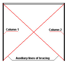
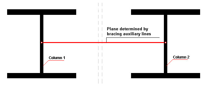
- First column, second column – elements connected with the bracing (see the drawing above).
- Limitations – all the top or bottom limits of the bracing (for example, the beam in the drawing above).
As an example, to define the bracing shown in red in the left part of the drawing below, define the elements displayed on the right.
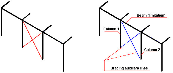
Note: The order in which columns and auxiliary lines are selected has an effect on the bracing model. The point of intersection of the axis of the first column and the first auxiliary line is regarded as the reference point of the bracing.