After defining the continuous footing dimensions, click Next. The following dialog displays:
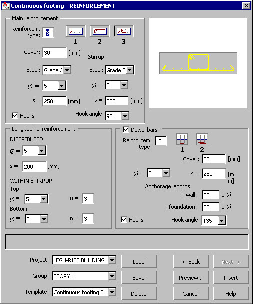
The top of the dialog includes parameters of main reinforcement of the continuous footing. There are three types of main reinforcement available:
 - bottom reinforcement
  - stirrup reinforcement
  - bottom reinforcement and stirrup.
For the main (bottom) reinforcement the following parameters should be specified:
- Steel grade
- Reinforcement cover
- Bar diameter and spacing
- Hook angle, if the Hooks option is selected; the following hook bend angles are available: 90, 135 and 180; if the Hooks option is cleared, hooks will not be generated.
For stirrup reinforcement the following parameters should be specified:
- Steel grade
- Bar diameter
- Stirrup spacing.
The middle part of the dialog includes parameters for defining longitudinal reinforcement of a continuous footing. When defining bottom reinforcement, the following parameters of distributed reinforcement should be specified for longitudinal reinforcement:
- Bar diameter
- Reinforcement spacing.
When defining stirrup reinforcement, the following parameters should be specified for longitudinal reinforcement (reinforcement is positioned within a stirrup):
- Bar diameter
- Number of bars in the upper or lower part of a stirrup.
The bottom right part of the dialog displays reinforcement parameters of the connection: continuous footing to wall. Parameters of this reinforcement type are available (and only then dowel bar reinforcement is generated) if the Dowel bars option is selected. For this reinforcement type the following parameters should be specified:
- Reinforcement scheme for the continuous footing-wall connection; the following types of reinforcement are available:
-
- Steel grade, bar cover and spacing
- Lengths of bar anchorage in a wall and a foundation (the length of anchorage in a foundation is available to the second type of the continuous footing-wall connection); if '=' is entered before a number in the text field, the anchorage length is defined as a segment length and not as a multiple of the diameter
- Hook angle for dowel bars of the continuous footing-column connection, if the Hooks option is selected; the following hook angles are available: 90, 135 and 180; if the Hooks option is cleared, hooks will not be generated.
Units used to define geometry and reinforcement of a continuous footing are set in the Job preferences dialog.
The bottom of the dialog includes selection lists used to define a hierarchy of defined projects and templates; the following rules apply while creating the hierarchy:
- a project is a component superior to a group in the hierarchy
- several different groups may be defined in a project
- each group may include many templates.
Such hierarchy makes it easier to manage structure elements included in a project; it is also simpler to copy a project between two users (computers used by users), by selecting the project folder hierarchy with all groups and templates included.
You can define an arbitrary hierarchy; the following hierarchy can be used as an example:
- Project - High-rise building
- Group - Foundations
- Template - Continuous footing 01.
The Template list includes user-defined templates (schemes) of continuous footings and their reinforcement. After defining the continuous footing geometry and reinforcement, it is possible to save these settings by specifying a name in the Template field and clicking the Save button (Note: a template is saved in a selected group and a selected project). After defining the continuous footing reinforcement and selecting the name of a saved template (in a selected project and a selected group), all parameters in the dialog are set exactly as they are defined in the template.
To open a template saved in a selected project and a selected group, click Load. To delete a selected template assigned to a selected project and a selected group, click Delete.
Templates saved in the macros for formworks of structure elements are available and can be loaded to the corresponding reinforcement macros. Once such a template is loaded, the Geometrytab sets parameters of the structure element geometry saved in the template.
The following buttons are located at the bottom of the dialog:
- Preview - Click to display the defined continuous footing and reinforcement
- Back < / Next > - Click to open the dialog on the previous / next tab
- Insert - Click to place the defined continuous footing and reinforcement in a drawing. The number of reinforcement positions and locations for the defined continuous footing in a drawing should be defined; together with a drawing of a continuous footing. A reinforcement table compliant with the settings specifed in the Job preferences dialog is inserted.