To load a drawing made in an RC module of Autodesk Robot Structural Analysis (beams, columns, spread footings, etc.), follow the steps below:
- Run the option:
Menu: Reinforcement > Insert drawing from Robot
Ribbon: ASD - Reinforcement > Tools > Insert drawing from Robot
Toolbar: Definition-bars > Insert drawing from Robot

Command line: RBCR_TOOL_IMPORT_RM.
-
In the Open dialog (shown below), select a drawing from the tree located in the right-hand side of the dialog (in this case these are Drawing1 and Drawing2 on the standard level, belonging to the RC Beams project).
Note: If the Import of printouts option is selected, then drawings prepared for printing in Robot are loaded.
-
Click Open; the selected drawings of an RC beam are loaded to Autodesk AutoCAD Structural Detailing - Reinforcement. In the Object Inspector dialog, on the Positions tab for each drawing, positions are created that include the appropriate views of the RC beam elements (as shown below).
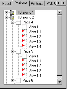
In Autodesk AutoCAD Structural Detailing - Reinforcement there is a possibility to edit the loaded drawings and to prepare final drawings of RC structure elements.