The following example illustrates the generation of drawings of a spread footing and an RC column generated with the use of the macros available in Autodesk AutoCAD Structural Detailing - Reinforcement. (Use the Model tab to define which views display in the illustration).
The first stage of drawing generation is to create views in the model space. Create views for projections of the spread footing and the column as follows:
- Click
 (Create View).
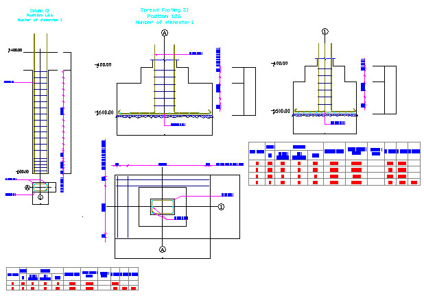
 - Select the views, e.g.: a view of the column with a reinforcement table (see the drawing below). Note: A column view and a table view can be created separately (the table and the column in separate views).
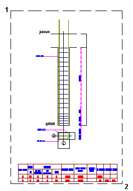
- In the command line, enter a view name, e.g. Column_elevation_section, and click ENTER.
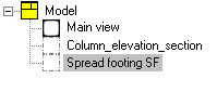
- Select the default scale value 1:20, and press ENTER; the name of the defined view appears on the Positions tab in the Object Inspector dialog.
- Use the same method to create a view of the spread footing projections (enter Spread footing SF1 for name, and use the default scale).
The second stage of drawing generation is to move the created views to the printout layout. Place the views in the printout layout as follows:
- Click the Printouts tab in the Object Inspector dialog; add a new printout tab, e.g. template A1 ASD.
- Right-click the new tab (A1 ASD), and click the Activate option from the context menu.
- Move to the Positions tab in the Object Inspector dialog.
- Right-click the column view (the view Column_elevation_section), and click the Add to current printout option from the context menu.
- Indicate the location of the view in the printout layout.
- Use the same method to place the spread footing projections on the printout.
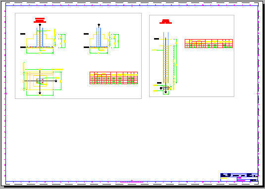
The generated printout (the final drawing) is shown below.