Use this option to define the distribution of wire fabrics for 2D contours (e.g. RC slab). There are several ways to access this option:
- Menu: Reinforcement > Surface reinforcement - wire fabrics
- Ribbon: ASD - Reinforcement > Definition - reinforcement > Surface reinforcement - wire fabrics
- Toolbar: Definition - wire fabrics > Surface reinforcement - wire fabrics

- Command line: RBCR_NETD_RECT.
After selecting the Surface reinforcement - wire fabrics option, the following dialog displays:
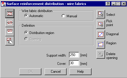
The dialog is divided into three main parts:
- The left side of the dialog contains four icons which specify the type of distribution:
 - Distribution A - wire fabric distribution within a span (within the defined contour e.g. plate span or wall)
  - Distribution B - wire fabric distribution above the intermediate support (with respect to the support axis)
  - Distribution C - wire fabric distribution above the extreme support (along the support edge)
  - Distribution D - any manner of wire fabric distribution (without the necessity to define a contour) without trimming wire fabrics. There are two modes of defining surface distribution available:
- Automatic mode - an indicated contour is detected automatically and wire fabrics are trimmed to fit the contour
- Manual mode - wire fabrics are distributed manually and timmed automatically to fit the contour.
For both modes, identical methods of wire fabric definition are available.
- In the middle of the dialog, the parameters used to define a selected distribution type are available:
- Distribution A
The top of the dialog includes options used to define the distribution region or opening(s); there are edit fields available used to define values of cover for wire fabrics and support width.
When starting definition of a distribution contour, the Opening option is inaccessible, whereas the Distribution region option is active and selected. Once the contour definition is complete, the Distribution region option is no longer active, whereas the Opening option becomes active and selected. You can then define an opening contour within the earlier-defined contour; a number of openings are determined.
- Distribution B
The following options are available:
- Edit field used to define the support width
- Edit fields used to define the value informing how far the wire fabric extends outside the support face (in both directions).
- Distribution C
The following options are available:
- Edit field used to define the cover value for wire fabrics
- Edit field used to define the support width
- Edit field used to define the value informing how far the wire fabric extends outside the support face.
- Distribution D
The options in the middle of the dialog are inaccessible.
There are two reasons for defining support width:
- Contour within which wire fabric is to be distributed is an external contour of a slab or wall; definition of a support width value models the support (wall) - within the support region a wire fabric will not be generated
- After determining the support width, overhangs are defined automatically - when defining reinforcement above supports (distribution B or C), they are recognized automatically.
- Distribution A
- The right side of the dialog contains several icons used to specify a region of wire fabric distribution:
- for Distribution A
 - Select (selects directly a region defined as rectangle, polygon, circle or indicates the existing defined distribution region)
  - Pick point (indicates an internal point for a closed region; as a result of the operation, the region contour is detected)
  - Diagonal (determines rectangular region by means of defining its diagonal)
  - Region (defines closed region by means of a broken line)
  - Delete opening (allows deleting an earlier-defined opening contour)
 - for Distribution B and C - Select (selects directly one edge of a region defined as line or support)
 - 2 Points (indicates two points determining the axis of a rectilinear support)
 In the dialog, you can define dimensions (apart from a cover value and width support) which inform how far a wire fabric extends outside the support face.
- for Distribution D
Icons are inaccessible. Click OK, to switch to distribution definition (without definition of a region).
- for Distribution A
Once the OK button is clicked, the Wire fabric distribution - manual mode or the Wire fabric distribution - automatic mode dialog opens.
The bottom of the dialog displays a description of the option selected.
See also: