Define a linear element as follows:
- Select the option: Create linear element
 .
. - In the Create linear element dialog, specify the following parameters:
- Element name: B2 Beam Section
-
Name of the folder where to the element will be saved
-
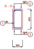
Click Select objects; and select the already-existing RC beam cross-section (see the drawing below)
-
Click Save; the selected object (RC beam cross-section) will be saved to database
To insert a linear element into a drawing, do the following:
- Select the option: Insert linear element
 .
. - In the Insert linear element dialog, select the linear element defined above (indicate it in the tree located in the left part of the dialog ) - see the drawing below
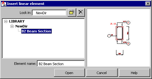
- Click Open; theLinear element parameters dialog displays, where the following parameters are specified:
- length of linear element: e.g. 3000 mm
- spacing of elements over the length: e.g. 250 mm
- Click Insert in theLinear element parameters dialog, and then indicate the location of the drawing.
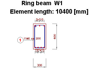
An example drawing of a linear element is shown below: