After defining the dimensions of the retaining wall reinforcement, click Next. The following dialog displays:
The options used to define the retaining wall reinforcement are provided on two tabs in the dialog.
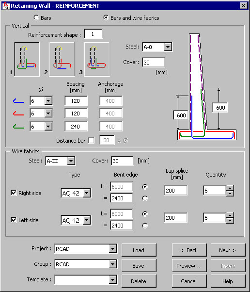
The first tab is shown in the drawing above. Main reinforcement of a retaining wall is generated with the use of:
- Reinforcing bars
- Reinforcing bars and wire fabrics.
The following parameters of vertical reinforcement are defined in the upper part of the dialog:
- Type of vertical reinforcement:
Selected option: Bars
1 -

2 -

3 -

Selected option: Bars and wire fabrics:
1 -

2 -

3 -

- Parameters for vertical bars - the following parameters are specified for each reinforcement shape (bars are marked with colors):
- Steel grade
- Cover
- Reinforcement diameter
- Bar spacing
- Bar anchorage
Note: Not all reinforcing bars are available for each reinforcement shape (type).For the first reinforcement type the Distance bar option is available; if selected, additional reinforcing bars with the length given in the edit field, are generated in the upper part of a retaining wall (see the drawing below).

- Parameters for wire fabrics (wire fabrics are placed on the right / left side of the wall)
The following parameters should be defined for each reinforcement shape:
- Steel grade
- Cover
- Wire fabric type (on the right / left side of the retaining wall)
- Wire fabric edge to be bent (on the right / left side of the retaining wall)
- Reinforcement lap splice (it refers to connection of wire fabrics along the length of the retaining wall)
- Number of wire fabrics along the length of the retaining wall
After defining the parameters for the main reinforcement of the retaining wall and clicking Next, the following dialog displays. This is the second tab used for defining reinforcement of the retaining wall.
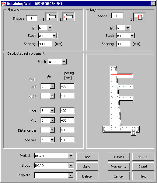
The following parameters are specified in the lower part of the dialog:
- Reinforcement of shelves:
reinforcement shape:
 or
or 
reinforcement parameters: diameter, steel grade and spacing of reinforcing bars
- Distributed reinforcement:
Steel grade
Diameter and spacing of reinforcing bars for:
- Wall (from the left and right)
- Foot
- Key
- Shelves
- Key reinforcement:
reinforcement shape:

reinforcement parameters: diameter, steel grade and spacing of reinforcing bars.
Units used to define the geometry and reinforcement of a retaining wall are set in the Job preferences dialog.
At the bottom of the dialog, is a selection lists used to define a hierarchy of defined projects and templates; the following rules apply while creating the hierarchy:
- a project is a component superior to a group in the hierarchy
- several different groups may be defined in a project
- each group may include many templates.
Such hierarchy makes it easier to manage structure elements included in a project. It is also simpler to copy a project between two users (computers used by users), by copying a whole folder with the project name for the entire project hierarchy with all groups and templates.
You can define an arbitrary hierarchy; the following hierarchy can be used as an example:
- Project - Structures
- Group - Foundations
- Template - Retaining wall 01.
The Template list includes user-defined templates (schemes) of retaining walls and their reinforcement. After defining the retaining wall geometry and reinforcement, it is possible to save these settings by specifying a name in the Template field and clicking the Save button (Note: a template is saved in a selected group and a selected project). After defining the retaining wall reinforcement and selecting the name of a saved template (in a selected project and a selected group), all parameters in the dialog are set exactly as they are defined in the template.
To open a template saved in a selected project and a selected group, click Load. To delete a selected template assigned to a selected project and a selected group, click Delete.
Templates saved in the macros for formworks of structure elements are available and can be loaded to the corresponding reinforcement macros. Once such a template is loaded, the Geometrytab sets parameters of the structure element geometry saved in the template.
The following buttons are located at the bottom of the dialog:
- Preview - Click to display the defined retaining wall and reinforcement
- Back < / Next > - Click to open the dialog on the previous / next tab
- Insert - Click to place the defined retaining wall and reinforcement in a drawing. The number of reinforcement positions and locations for the defined retaining wall in a drawing should be defined; together with a drawing of a retaining wall. A reinforcement table compliant with the settings specifed in the Job preferences dialog is inserted.